Copyright © Siemens AG 2016. All rights reserved
250
ERTEC 200P-2 Manual
Technical data subject to change
Version 1.0
Reload_2
78
9.984 µs (CLOCK2)
9.360 s
Reload_3
390
42.42 µs (CLOCK3)
39.30 s
Reload_4
2
99.84 µs (CLOCK4)
93.60 s
Reload_5
6
299.5 µs (CLOCK5)
280.78 s
Reload_6
30
1.5 ms (CLOCK6)
1.406 ms
Reload_7
40
2.0 ms (CLOCK7)
1.875 ms
Table 18:
Sample filter times for I-filter
The filter time is calculated by multiplying the division factor (cascaded from divider 3) by
16xTPCLK, as the filter system means that the output value can only change for every
16th clock. The filter times are as follows:
min.
128 ns
e.g. when:
IN_Delay_x
=0 &
FILT_Reload_0
=0
max.
134 ms
e.g. when:
IN_Delay_x
=7 &
FILT_Reload_3
=0x3FF &
FILT_Reload_7
=0x3FF
The maximum (total) throughput time through the filter module is if configured equal to
the filter time plus 16 ns for two-stage synchronization. The minimum (total) throughput
time (see Table 18) in this configuration depends on the CLOCK0 to CLOCK7 clock sig-
nal jitter.
2.3.10.1.1
Operating Principle of the RC Filter
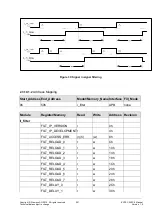
The most significant bit in the 5-bit counter is the filtered output signal (
D_IN_Delay
).
If the input signal (
D_IN_SYN
) switches to "High", the counter starts to count up. If the
counter status changes from '15' to '16', the counter value is automatically set to '31'
('0x1Fh'). When the counter reaches '31', the output signal (
D_IN_Delay
) is also set to
"High". The counter value remains at '31' until the input signal (
D_IN_SYN
) changes from
"High" to "Low".
If the input signal (
D_IN_SYN
) switches to "Low", the counter starts to count down. If the
counter status changes from '15' to '16', the counter value is automatically set to '0'
('0x00h'). When the counter reaches '0', the output signal (
D_IN_Delay
) is also set to
"Low". The counter value remains at '0' until the input signal (
D_IN_SYN
) changes from
"Low" to "High".
Brief signal changes during the counting phase cause the counter to count either up or
down in line with its signal state, i.e. the counter does not start from '0' following a signal
change (that would be a signal delay, not filtering).
The filter structure therefore acts as an RC circuit or digital I-controller.


