Copyright © Siemens AG 2016. All rights reserved
404
ERTEC 200P-2 Manual
Technical data subject to change
Version 1.0
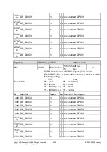
15dt1
4
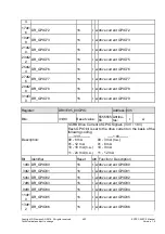
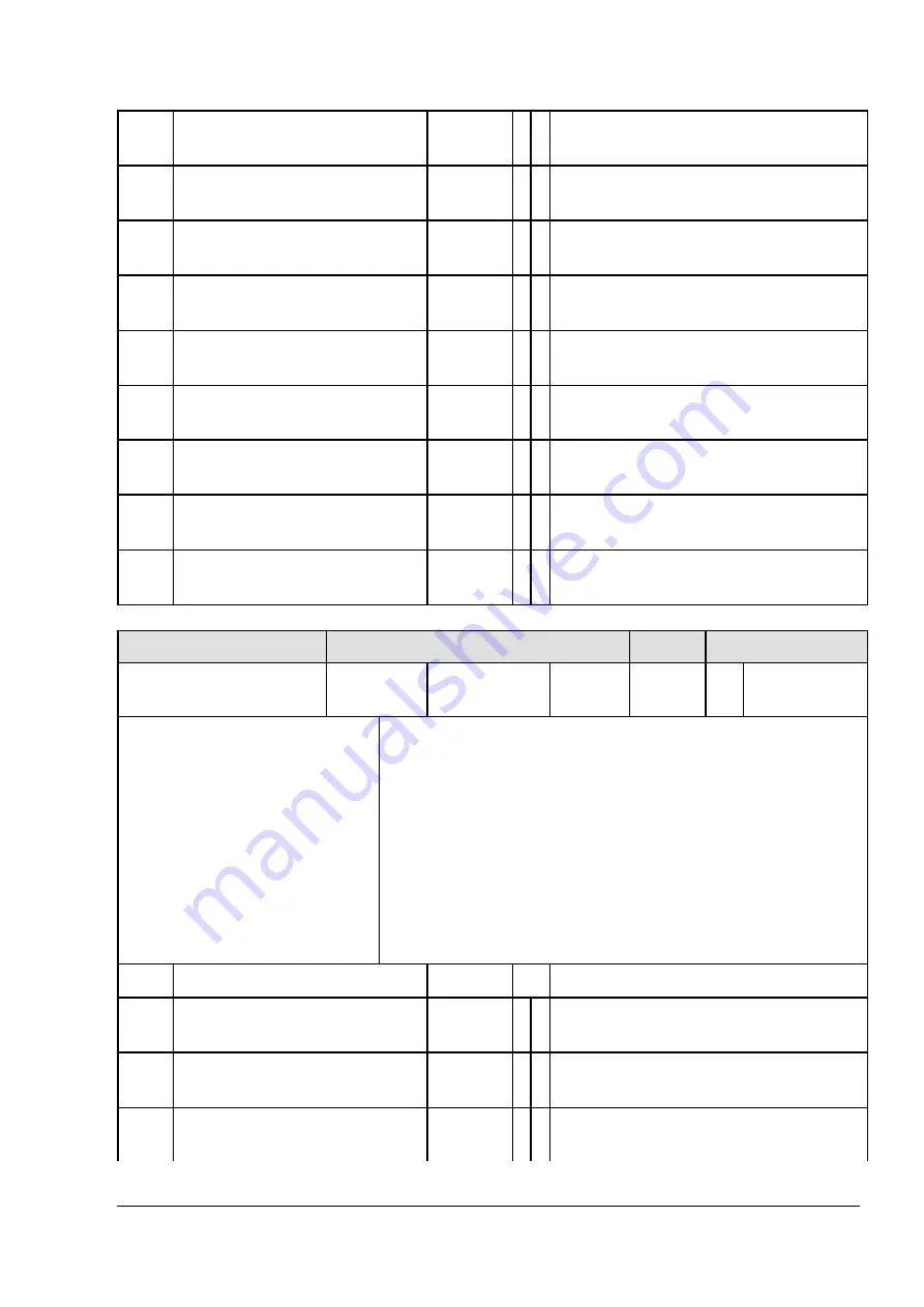
DR_GPIO87
1h
r w drive current GPIO87
17dt1
6
DR_GPIO88
1h
r w drive current GPIO88
19dt1
8
DR_GPIO89
1h
r w drive current GPIO89
21dt2
0
DR_GPIO90
1h
r w drive current GPIO90
23dt2
2
DR_GPIO91
1h
r w drive current GPIO91
25dt2
4
DR_GPIO92
1h
r w drive current GPIO92
27dt2
6
DR_GPIO93
1h
r w drive current GPIO93
29dt2
8
DR_GPIO94
1h
r w drive current GPIO94
31dt3
0
DR_GPIO95
1h
r w drive current GPIO95
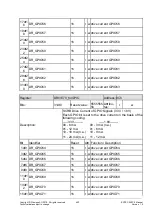
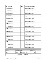
Register:
PULL15_0GPIO
Address: 94h
Bits:
31dt0
Reset value: 0h
Attribu-
tes:
rh
w
Description:
SCRB Pull GPIO Signals
Each GPIO bit is set to the pull resistors on the basis of
the following coding
00 - highZ
01 - Pull-up
10 - highZ
11 - Pull-down
If the PAD is switched to output, the pull resistors are au-
tomatically deactivated
Reset value does not apply as the register is loaded in
accordance with the function set with CONFIG.
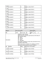
Bit Identifier
Reset Attr. Function / Description
1dt0 PR_GPIO0
xh
r
h
w pull control GPIO0
3dt2 PR_GPIO1
xh
r
h
w pull control GPIO1
5dt4 PR_GPIO2
xh
r
h
w pull control GPIO2

