Copyright © Siemens AG 2016. All rights reserved
427
ERTEC 200P-2 Manual
Technical data subject to change
Version
1.0
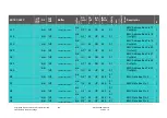
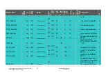
3.2 Detailed Signal Description
Active level low = Signal name X….;
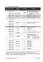
*) Driver power of the EMC signals can be set on a group-specific basis (G1 – G11) in the SCRB register SCRB_DRIVER_EMC
(see 2.3.10.9.15.1)
**) Driver power of GPIO(31:0) and XHIF interface (GPIO95:32); can be set on a signal-specific basis with the
SCRB_DRIVEx_yGPIO SCRB registers (see
2.3.10.9.15.1)
**) Pull circuit for GPIO(31:0) and XHIF interface (GPIO95:32); can be set on a signal-specific basis with the SCRB_PULLx_yGPIO
SCRB registers (see
2.3.10.9.15.2)
ERTEC 200P
C
T
R
L
_
S
T
B
Y
x
Dir
3V3
1V8
Buffer
B
u
ff
e
r
D
ir
DS
(mA
)
CL
(pF
)
int.
Pul
l
fout
(MHz
)
a
c
ti
v
it
y
L
o
w
N
o
is
e
S
c
h
m
it
t
T
ri
g
g
e
r
Description
#
EMC
A0
-
bidi
1V8
TWC1BC18ALV04SZ
bid
i
G2
*)
42
-
42
0.1
-
EMC Address Bus Pin 0
REE DFT Input
1
A1
-
bidi
1V8
TWC1BC18ALV04SZ
bid
i
G2
*)
42
-
42
0.1
-
EMC Address Bus Pin 1
REE DFT Input
1
A2
-
bidi
1V8
TWC1BC18ALV04SZ
bid
i
G2
*)
42
-
42
0.1
-
EMC Address Bus Pin 2
REE DFT Input
1
A3
-
bidi
1V8
TWC1BC18ALV04SZ
bid
i
G2
*)
42
-
42
0.1
-
EMC Address Bus Pin 3
REE DFT Input
1
A4
-
bidi
1V8
TWC1BC18ALV04SZ
bid
i
G2
*)
42
-
42
0.1
-
EMC Address Bus Pin 4
REE DFT Input
1
A5
-
bidi
1V8
TWC1BC18ALV04SZ
bid
i
G2
*)
42
-
42
0.1
-
EMC Address Bus Pin 5
REE DFT Input
1


