Copyright © Siemens AG 2016. All rights reserved
434
ERTEC 200P-2 Manual
Technical data subject to change
Version
1.0
ERTEC 200P
C
T
R
L
_
S
T
B
Y
x
Dir
3V3
1V8
Buffer
B
u
ff
e
r
D
ir
DS
(mA
)
CL
(pF
)
int.
Pul
l
fout
(MHz
)
a
c
ti
v
it
y
L
o
w
N
o
is
e
S
c
h
m
it
t
T
ri
g
g
e
r
Description
#
used!
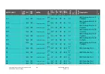
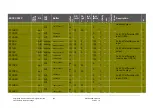
XCS_SDRAM
-
out
1V8
TWC1BC18ALV04SZ
bid
i
G9
*)
42
-
5
0.1
-
Chip select for SDRAM
1
XRAS_SDRAM
-
out
1V8
TWC1BC18ALV04SZ
bid
i
G9
*)
42
-
5
0.1
-
Row address strobe
1
XCAS_SDRAM
-
out
1V8
TWC1BC18ALV04SZ
bid
i
G9
*)
42
-
5
0.1
-
Column address strobe
1
XWE_SDRAM
-
out
1V8
TWC1BC18ALV04SZ
bid
i
G9
*)
42
-
5
0.1
-
Write enable for SDRAM
1
XAV_BF
-
bidi 1V8
TWC1BC18ALV04SZ
bid
i
G11
*
)
42
UP
5
0.1
-
Address Valid BurstFlash
Boot(4)
1
XRDY_BF
-
in
1V8
TWC1IC18AS
-
-
UP
-
-
-
Ready BurstFlash
EXT_DRIVER_DISABLE
_CS0
1
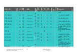
CLK_O_BF0
-
out
1V8
TWC1BC18ALV04SZ
bid
i
G10
*
)
42
-
125
1
-
Feedback clock output
1
CLK_O_BF1
-
out
1V8
TWC1BC18ALV04SZ
bid
i
G10
*
)
42
-
125
1
-
clock for the BurstFlash
device
1
CLK_O_BF2
-
out
1V8
TWC1BC18ALV04SZ
bid
i
G10
*
)
42
-
125
1
-
clock for the BurstFlash
device
1
CLK_I_BF
-
in
1V8
TWC1IC18AS
bid
i
-
-
-
-
-
-
Feedback clock for syn-
chronization of read data.
MUST be connected,
even if BurstFlash is not
1


