Copyright © Siemens AG 2016. All rights reserved
452
ERTEC 200P-2 Manual
Technical data subject to change
Version
1.0
3.3.1 EMC Timing
3.3.1.1 SRAM Timing
The use of XRDY_PER is optional and can be enabled with ASYNC_BANKx.EW. Wait-
States can be inserted if XRDY_PER is used.
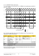
For the asynchronous SRAM interface an
“active interface”
is selectable. Active interface
means that at the end of a transfer the data bus is actively driven high for one AHB clock
cycle. This is necessary together with the use of internal PullUps to speed up the reloading
of the wiring capacity.
After the active phase the internal PullUps are driving the data bus and there is no need
for external PullUps on the board.
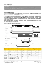
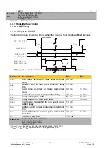
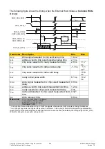
3.3.1.1.1 SRAM Timing for read access
Parame-
ter
Description
Min
Max
depends on Register
Note
t
R_SU
Read Setup-
Time
0 Tc – 4.5
ns
15 Tc + 4.8
ns
ASYNC_BANKx.R_SU
1)
t
R_STROBE
Read Strobe-
Time
1 Tc – 4.2
ns
64 Tc + 4.4
ns
ASYNC_BANKx.R_STR
OBE
1)
t
R_HOLD
Read Hold-Time 1 Tc – 4.8
ns
8 Tc + 4.4
ns
ASYNC_BANKx.R_HOL
D
1)
t
SU_DATA
Data
Setup
Time 5.4ns
t
H_DATA
Data Hold Time
2.1 ns
Important:
To achieve the timing below, configure EXTENDED_CONFIG.SODM = '0' (default value).
EXTENDED_CONFIG.SODM = '1' is not permitted


