Copyright © Siemens AG 2016. All rights reserved
183
ERTEC 200P-2 Manual
Technical data subject to change
Version 1.0
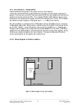
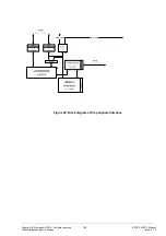
The figure below shows the structure of the XHIF, which consists of two individual XHIF
modules (XHIF_0/1) (2x 4 pages of 2 MByte each).
The XHIF module (XHIF_0 or XHIF_1) is selected with the XHIF_SEG_2 pin. The XHIF
interface is switched to the selected XHIF module. Access to the AHB interface is with
arbitration. The pins XHIF_SEG_0 and XHIF_SEG_1 address the corresponding pages
of an XHIF module.
The XHIF configuration (XHIF_ACC_Mode, XHIF_POL_RDY, XHIF_CPU_Width) is the
same for both XHIF modules and is connected straight to both modules (source: Config-
Pins or XHIF_Control register). The XHIF interrupt (XHIFerr_IRQ) is connected from each
module with an OR logic operation and connected externally (to the event unit in PER-IF).
2.3.6.2 Function Description (XHIF)
XHIF0, 1 is an interface module that enables an external CPU to access the AHB bus as
master over a memory interface. The basic features of the interface module are as fol-
lows:
32/16 and 8-bit CPUs can be connected with an address range (A0 to A22) of 10 to 23
address bits (1k to 8M) (
however, only 16/32-bit CPUs are supported in the ERTEC
200P)
Addresses A21 (XHIF_SEG0) and A22 (XHIF_SEG1) are used to select the 4
possible pages with an address range of 256 bytes to 2 MByte.
The interface module can be configured by the external CPU over a 16-bit or 32-bit data
bus.
The interface module can also always be configured with the internal ARM926 APB bus.
XHIF interface timing is asynchronous to the AHB bus clock.
Areas in the AHB address range (pages) can be configured for access by the external
CPU (XHIF internal paging register). ERTEC 200P address mapping (see 2.4.4) is de-
signed to ensure that all relevant AHB address ranges can be configured over the 8 pag-
es (8 x 2MByte) during ERTEC 200P operation.
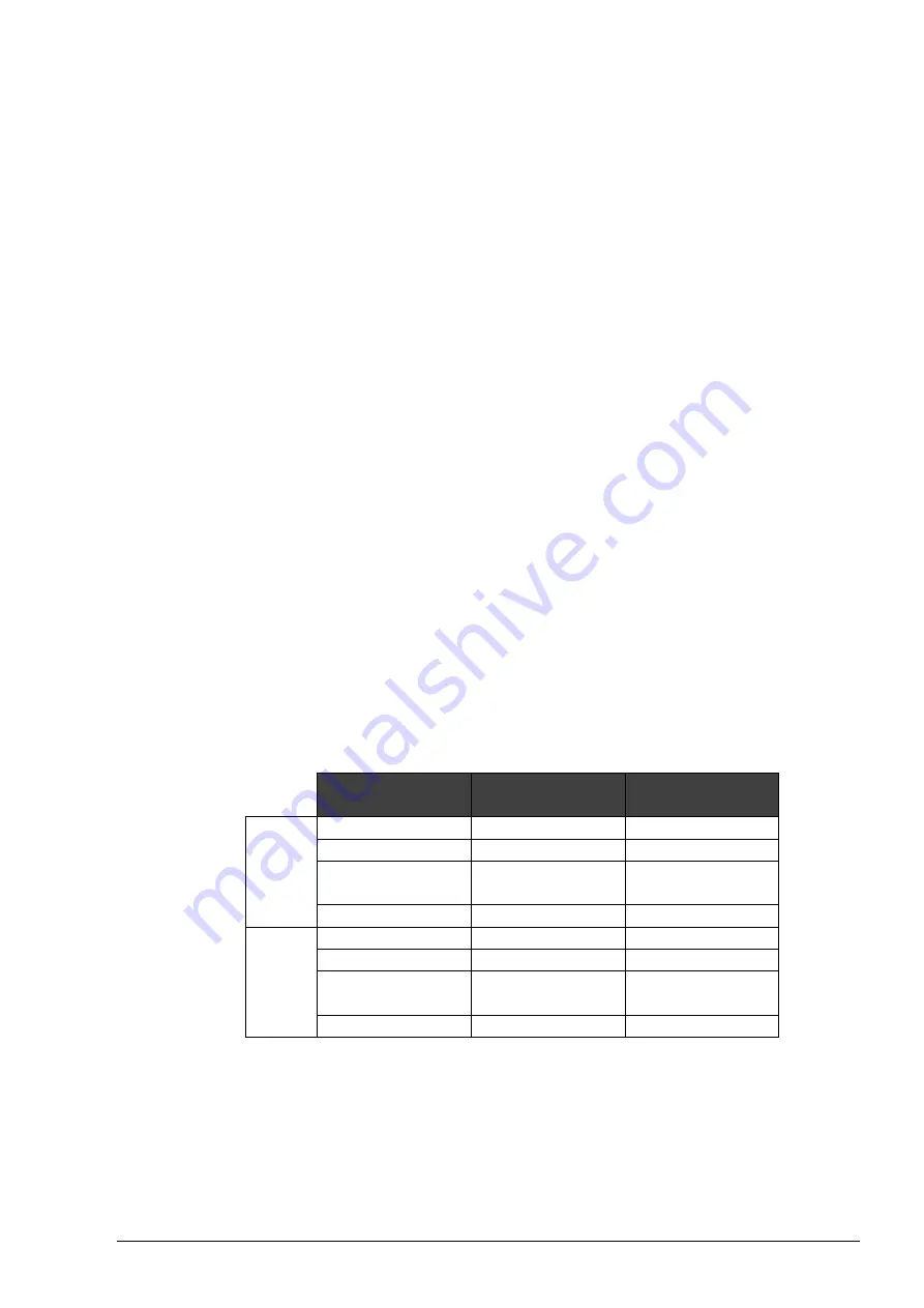
Below is an example of possible page configuration:
XHIF address
range
AHB module
AHB address
range
XHIF0 Page 0
APB peripherals 1 MByte
Page 1
Profinet IP
2 MByte
Page 2
Peripheral inter-
face
1 MByte
Page 3
GDMA
1 MByte
XHIF1
Page 4
Reserved
2 MByte
Page 5
SDRAM (EMC)
2 MByte
Page 6
D-TCM
(ARM926)
2 MByte
Page 7
SRAM (EMC)
2 MByte
The AHB master interface is based on the AHB standard 2.0 AHB-Lite protocol.
The XHIF module has only one clock source, which must correspond to the frequency of
the AHB/APB system connected.
Single read and write commands are supported, but burst mode is not.
The XHIF module only supports little-endian mode (least significant byte at the lower
memory address)


