Copyright © Siemens AG 2016. All rights reserved
366
ERTEC 200P-2 Manual
Technical data subject to change
Version 1.0
2.3.10.9.2
Boot Register
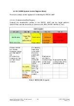
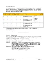
The required boot mode is saved in the BOOT_REG boot register. Some of the pins of
the EMC interface (see table) are assigned to the boot register bits 0...4. The EMC pins
are latched to the boot register boot register during an active XRESET reset and return to
their normal function with an inactive reset.
BootPin(3)
= A[16]
BootPin(2)
= A[15]
BootPin(1)
=XOE_DRIVER
BootPin(0)
= DTXR
Boot
mode
Booting…
BootPin(4)
= XAV_BF
1
0
0
1
1
External NOR flash (16-bit)
1)
,
ASYNC_ADDR_MODE
= 1
Compile
mode
1
2)
Copy mode
0
1
0
1
0
2
External NOR flash (32-bit)
1)
,
ASYNC_ADDR_MODE
= 1
Compile
mode
1
2)
Copy mode
0
1
1
0
1
5
SPI master (RD Cmd: 0xE8)
x
1
1
1
0
6
SPI master (RD Cmd: 0x03)
x
1
1
1
1
7
XHIF (ext. host)
x
1)
The secondary boot loader is run straight from the NOR flash and not from the TCM. The default mode,
i.e. without external resistors, is a NOR flash with an access width of 32 bits and is selected with the internal pull
circuit (highlighted in
blue
).
2)
Code mode is not supported
Table 22: Bootmodi adjustment
2.3.10.9.3 Config Register
Global use cases and different test modes can be set with EMC pins that are latched in
the CONFIG_REG register during an XRESET active PowerOn reset. These pins resume
their EMC function in normal mode once the reset is cleared.
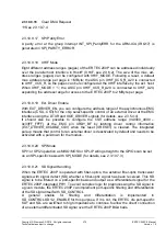
CONFIG(0): Enable REF_CLK output (25 MHz) or disable (tristate).
CONFIG(1): ARM clock 125 / 250 MHz.
CONFIG(2): PLL bypass: A 125 MHz clock is supplied straight over BYP-CLK and the
PLL is bypassed. BYP-CLK is usually used as the F-counter clock source.
All internal clocks that operate at 125/250 MHz are set to 125 MHz (fixed
setting). CONFIG(1) must also be set to '0'.
CONFIG(6-3): XHIF interface setting: (off, 16/32-bit, ARM926 trace port)
XHIF_XRDY setting: (low-active, high-active)
XHIF_XWR setting: (Wr or Read/Write Control)
GPIO31-0 setting: GPIO, PHY debug port


