Copyright © Siemens AG 2016. All rights reserved
478
ERTEC 200P-2 Manual
Technical data subject to change
Version
1.0
4.2.2 Circuit with External Crystal Oscilllator
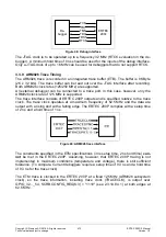
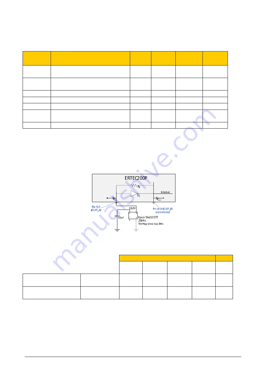
If the ERTEC 200P is wired with an external crystal oscillator at CLKP_A instead of a crys-
tal (see 4.2) (
important:
CLKP_B must
not
be connected - open), the external crystal
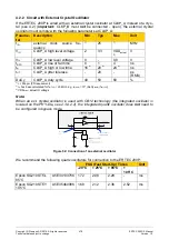
oscillator must comply with the following parameters at CLKP_A:
Parame-
ter
Description
Min
Typ
Max
Unit
f
IN
external clock source fre-
quency
1)
25
1)
MHz
V
IH
CLKP_A high level voltage
2
3,3
VDD
actual
3)
V
V
IL
CLKP_A low level voltage
0
-
0,8
V
t
RFC
CLKP_A rise or fall time
0
1
4
ns
t
w
CLKP_A high or low time
16
2)
20
2)
24
2)
ns
t
JIT
CLKP_A jitter tolerace
-
20
-
ps
(RMS)
DuCy
CLKP_A duty cycle
40
50
60
%
1)
+/- 50ppm (PN requirement)
2)
t
w
has been calculated for f
IN(TYP)
= 25 MHz, e.g. t
w(MIN)
= 10* (DuCy
(MIN)
/ f
IN(TYP)
)
3)
VDD
actual
: actual IO voltage
Note:
When an ext.
crystal
oscillator is used with CB12 technology (the integrated oscillator is
located on the PHY-Die, see 2.3.9.2.2), the integrated quartz oscillator does not need to
be configured in bypass mode.
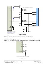
Figure 52: Connection of an external oscillator
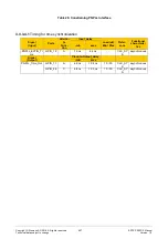
We recommend the following quartz oscillators for connection to the ERTEC 200P:
FSU (Fast Start-Up) Times
Unit
- 20°C
+ 25°C
+ 85°C
+
105°C
Epson SG210STF-L
85°C
A5E34133756 1.72
2.08
2.28
-
ms
Epson SG210STF-Y
105°C
A5E35460986 1.68
2.12
2.36
2.52
ms


