Copyright © Siemens AG 2016. All rights reserved
485
ERTEC 200P-2 Manual
Technical data subject to change
Version
1.0
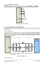
4.6.2.1 PHY-FX Wiring – not used
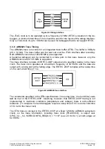
PxTDXP/N
Signals on unused FX port should be left open,
PxRDXP/N
and
PxSDXP/N
inputs should directly connected to GND, the GPIOs could used for alternate function.
PxRDXP
PxTDXP
GPIO(4) / GPIO(6)
GPIO(5) / GPIO(7)
open
PxTDXN
PxRDXN
PxFXEN
PxSDXP
PxSDXN
open
open
Alternate function
Alternate function
GND
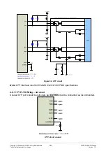
Figure 56: FX circuit unused pins
4.6.2.2 PHY-SD Wiring – Avago QFBR-5978AZ
The Avago QFBR-5978AZ has a single ended output and ERTEC 200P has a differential
LVPECL input.
4.6.2.2.1 PxSD circuit
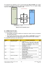
The following level translation circuit is recommended
by direct connecting of PxSD
signals.
Comparator should be placed near transceiver and PECL driver near ERTEC
200P. The 3,3V supply voltage tolerance for
POF transceiver and SD level translation
circuit
is limited to
+- 5%
.
SD level translation circuit
4.6.2.2.2 GPIO circuit


