Copyright © Siemens AG 2010. All rights reserved.
Page
10
ERTEC 400 Manual
Technical data subject to change
Version 1.2.2
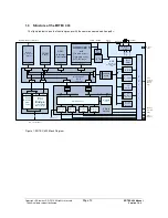
1.3 Structure of the ERTEC 400
The figure below shows the function groups with the common communication paths.
PCI
Bridge
(32 Bit, 66MHz)
Master-/Target
ARM -
Interrupt-
Controller
ARM 946ES
with
I-Cache
(8kByte)
,
D-Cache
(4kByte)
,
D-TCM
(4kByte)
AHB/APB
Bridge
GPIO
M
a
s
te
r
Slave
AHB-
W rapper
M aster
M aster
M a ster
P
P
o
r
t
s
APB
(Advanced
Peripheral Bus)
50M H z
32 Bit
7 6
52
PC I-/Local Bus
External Memory Interface
SRAM
(8 kByte)
Slave
2 x UART
SPI
Interface
2 x Tim er,
W atchdog,
F-Timer
7
A
R
M
9
c
lo
c
k
5
0
M
H
z
1
0
0
M
H
z
1
1
12,5M Hz
SC-Bu s (50MHz)
M C -Bu s (50MHz)
32 Bit
32 Bit
4 Port
Switch
Switch C ontrol
K-SRAM
192 kByte
Ethernet-
Port1
Ethernet-
Port2
Ethernet-
Port3
Ethernet-
Port4
32
7
Slave
JTAG / Debug
Ports
(serielle
SS, SPI,
W atch-
dog)
IRT-PLL-
Interface
7
7
RM II-
Interface
AH B-
W ra pper
Slave
M aste r
S
la
v
e
S
la
v
e
S
la
v
e
S
la
v
e
Boot-
RO M
S
la
v
e
S
la
v
e
7
7
BS-
TAP
1
Test
M ulti-Layer-
AHB
50 M Hz/32Bit
Local
Bus Unit
(LBU)
(16 Bit)
Memory-
Controller
(EMIF)
M aster
Slave
Sla ve
M UX/Arb.
Inpu t
stage
Inpu t
stage
Input
stag e
M U X/Arb.
M U X/Arb.
M UX/Arb.
D eco de
M
U
X
/A
rb
.
3
SM I
3
Reset
System
Control
Register
S
la
v
e
Clock-
Unit
REF_CLK
REF_CLK
ETM
Trace-
Port
Figure 1: ERTEC 400 Block Diagram


