Copyright © Siemens AG 2010. All rights reserved.
Page
43
ERTEC 400 Manual
Technical data subject to change
Version 1.2.2
4.5 Watchdog Timers
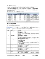
Two watchdog timers are integrated in the ERTEC 400. The watchdog timers are intended for stand-alone
monitoring of processes. The working clock of 50 MHz is derived from the PLL the same as the processor clock.
4.5.1
Watchdog Timer 0
Watchdog timer 0 is a 32-bit down-counter to which the WDOUT0_N output is assigned. This output can be used
at the GPIO[15]-pin as an alternative function (see GPIO and signal descriptions). The timer is locked after a
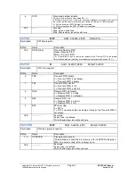
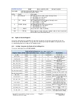
reset. It is started by setting the “Run/XStop_Z0” bit in the “CTRL/STATUS” watchdog register.
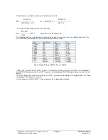
A maximum monitoring time of 85.89 s (at a resolution of 20 ns) can be assigned.
4.5.2
Watchdog Timer 1
Watchdog timer 1 is a 36-bit down-counter in which only the upper 32 bits can be programmed. The WDOUT1_N
output is assigned to watchdog timer 1. This output is not routed to the outside. Rather, it triggers a hardware
reset internally. The timer is locked after a reset. It is started by setting the “Run/XStop_Z1” bit in the
“CTRL/STATUS” watchdog register.
A maximum monitoring time of 1374.3 s (at a resolution of 320 ns) can be assigned.
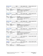
When the “LOAD” bit is set in the “CTRL/STATUS” watchdog register, both watchdog timers are reloaded with the
applicable reload values of their reload registers. In the case of watchdog timer 1, bits 35:4 are loaded with the
reload value. Bits 3:0 are set to 0.
The count values of the watchdog timers can also be read. When watchdog timer 1 is read, bits 35:4 are read out.
The status of the two watchdog timers can be read out in the “CTRL/STATUS” register.
4.5.3
Watchdog Interrupt
The WDINT interrupt of the watchdog is routed to the FIQ interrupt controller. The interrupt is only active (High) if
watchdog timer 0 is in “RUN mode” and watchdog timer 0 has reached zero. The exception to this is a load
operation with reload value = 0.
4.5.4
WDOUT0_N
The WDOUT0_N output is at Low after a reset. If watchdog timer 0 is set in RUN mode and the timer value does
not equal zero, the output changes to High. The output changes to Low again when the count has reached zero.
The output can also be reset by stopping and then restarting watchdog timer 0.
The signal can be used as an external output signal at the GPIO[15] port if the alternative function is assigned for
this pin. The output can thus inform an external host about an imminent watchdog event.
4.5.5
WDOUT1_N
The WDOUT_N signal is at High after a reset of when watchdog timer 1 goes to Stop. If watchdog timer 1 is
started, WDOUT1_N changes to Low when the timer reaches zero. It remains Low until watchdog timer 1 is
loaded with the reset value again by setting the “LOAD” bit. The exception is when reload value = 0 is loaded. A
hardware reset is triggered internally with WDOUT1_N.
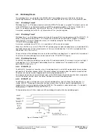
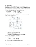
The figure below shows the time sequence of the watchdog interrupt and the two watchdog signals:
Figure 6: Watchdog Timing
XRESET
Run/XStop_Z1
WDINT
XWDOUT1
XWDOUT0
Counter0=0
Delete XWDOUT0
through Run/XStop_Z0 -> 0->1
Counter1=0
Trigger
(internal)
(internal)
Run/XStop_Z0
(internal)
//
//
//
//
//
//
//
//
//
//
//
//


