Copyright © Siemens AG 2010. All rights reserved.
Page
63
ERTEC 400 Manual
Technical data subject to change
Version 1.2.2
5 General Hardware Functions
5.1 Clock Generation and Clock Supply
The clock system of the ERTEC 400 basically consists of four clock systems that are decoupled through
asynchronous transfers:
•
ARM946E-S together with AHB bus, APB bus, and IRT
•
JTAG Interface
•
PCI bus
•
RMII/MII – interfacing of Ethernet MACs
5.1.1
Clock Supply in ERTEC 400
The required clocks are generated in the ERTEC 400 by means of internal PLL and/or through direct infeed.
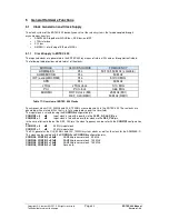
The following table provides a detailed list of the clocks:
MODULE
CLOCK SOURCE
FREQUENCY
ARM946ES
PLL
50/100/150 MHz (scalable)
AHB/EMIF/ICU
PLL
50 MHz
IRT (except MII/RMII)
PLL
50/100 MHz
APB
PLL
50 MHz
JTAG
JTAG clock
0-10 MHz
PCI
PCI clock
0-66 MHz
MII/RMII
RX/TX clock (MII)
REF_CLK (RMII)
25 MHz (MII)
50 MHz (RMII)
Table 17: Overview of ERTEC 400 Clocks
Synchronous clocks CLK_50MHz and CLK_100MHz are used primarily in the ERTEC 400. These clocks are
generated with an internal PLL that is, in turn, supplied by a quartz or oscillator.
The input clock is selected using the
CONFIG0
configuration pin.
CONFIG0 = 0
Input clock is fed with a quartz via the
CLKP_A
,
CLKP_B
pin.
CONFIG0 = 1
Input clock is fed with an oscillator clock via the
REF_CLK
pin.
In the case of direct infeed at the REF_CLK pin, the clock frequency can be set with the
CONFIG1
configuration
pin.
CONFIG1 = 0
50 MHz input clock
CONFIG1 = 1
25 MHz input clock
The PLL generates the CLK_50MHz and CLK_100MHz system clocks as well as the clock for the ARM946E-S.
This clock can be scaled with the
CONFIG3
and
CONFIG4
configuration pins.
CONFIG4, CONFIG3 = 00
ARM946 processor clock 50 MHz.
CONFIG4, CONFIG3 = 01
ARM946 processor clock 100 MHz.
CONFIG4, CONFIG3 = 10
ARM946 processor clock 150 MHz.
CONFIG4, CONFIG3 = 11
Reserved.


