Mounting / Installation
Mounting
5
26 | 62
Building Technologies
A6V10227639_k_en_--
Fire Safety
2016-11-28
5 Mounting / Installation
5.1 Mounting
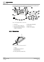
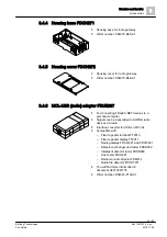
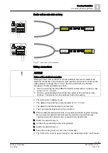
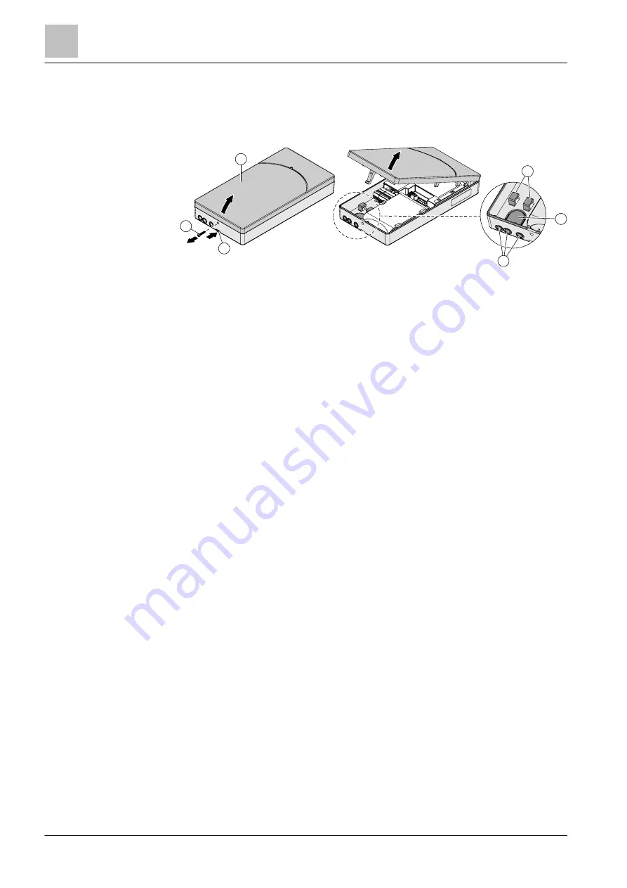
Figure 5: Installing the radio gateway
1 Housing cover
2 Screw
3 Lock
4 Strain relief fastenings
5 Cable entries
You have the radio gateway, battery pack, fixing screws, and cable tie to hand.
You have the device location plan to hand.
The connection cable has a conductor cross-section of 0.2…1.5 mm².
The lines to the installation location are installed.
Two fixing screws (Ø max. 4.3 mm) are to hand.
1. Determine the installation location:
– The housing must be positioned in accordance with the planning
specifications (make sure there is a wide radio range and that the housing
can be accessed easily).
– Make sure there is enough space for you to open the housing cover easily.
– The housing may be installed in any appropriate position.
2. Open the housing:
– Remove the screw (2) (A).
– Using a screwdriver to press the lock (3) into the housing (B) and unlock
the housing cover (1).
– Lift the housing cover (1) and remove it.
3. Remove the adhesive label bearing the serial number from the back box and
use it to mark the installation location on the device location plan.
4. In the back box, break out the plastic for the cable entry (5):
– Openings in the supporting surface for recess-mounted cables
– Openings in the narrow side for surface-mounted cables
5. Insert the cables into the back box.
A
B
C
2
1
3
4
5
5

