Structure and function
Function
3
21 | 46
Building Technologies
A6V10425652_en--_f
Fire Safety
2016-11-28
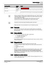
Operating condition
Flashing
mode
Graphic
New battery
IAI lights up
once for five
seconds
Battery is flat
IAI off
Several operating conditions may be indicated at the same time. This may lead to
the flashing patterns overlapping one another. The red LED indicator has priority
over the green LED indicator.
Flashing patterns with a higher frequency will overlap those with a lower
frequency, which means that the latter may no longer be discernible.
Not all fire control panels support the flashing patterns described.
Please also observe the documentation for your fire detection system.
3.3.3 Test mode
A test mode can be set on the control panel to test the radio manual call points.
When in test mode, alarms from the radio manual call points are not forwarded by
the control panel.
3.3.4 Alarm activation
l
Press the pressure point on the glass or plastic insert.
a
The plastic insert falls down or
a
The glass insert breaks.
a
The alarm is activated
After an alarm is activated, the manual call point must be reset to a state in which it
is ready for operation.
3.3.5 Diagnosis levels
The radio manual call point largely monitors its function by itself.
The following diagnosis levels are taken from the various control measurements:
Normal
Replacement necessary
Fault
When an error which impairs the radio manual call point's function occurs, a fault
message is signaled. To correct the cause of the fault, additional information is
available in the radio manual call point. This can be indicated with the Wireless
diagnostic tool. You will find more information in document A6V10425605. See the
chapter 'Applicable documents'.
3.3.6 Interface to service devices
The fire control panel or the software FXS2061-O Wireless diagnostic tool is used
to read out the detector data.
t
0
1
2
3
4
5
6
7
8
9
10
12
11
[s]
x1
t
0
1
2
3
4
5
6
7
8
9
10
12
11
[s]


