Mounting and installation
Installation
5
26 | 46
Building Technologies
A6V10425652_en--_f
Fire Safety
2016-11-28
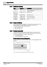
5.2 Installation
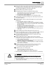
1 Back box
9 Screws for switching unit
2 Battery pack BAT3.6-10
1
10 Internal alarm indicator
3 Type plate with adhesive label
11 Plastic/glass insert
4 Battery holders
12 Housing cover
5 Battery connector
13 Retainer
6 Housing switching contact
14 Spring
7 Switching unit
15 Triggering device
8 Stop
1
not included in the scope of delivery
The flashing behavior of the internal alarm indicator is described in document
A6V10425652 in the 'Internal alarm indicator' chapter.
w
The back box is fastened.
w
You have a new, undamaged battery pack to hand.
w
You have key FDMK295 and a Phillips screwdriver to hand.
w
The radio gateway has been activated and switched to maintenance mode.
180°
4
9
8
13
8
12
10
2
14
3
11
7
8
9
5
6
1
11
11
15

