28
FLUDEX 4612 en
Operating instructions 10/2017
1)
2)
3)
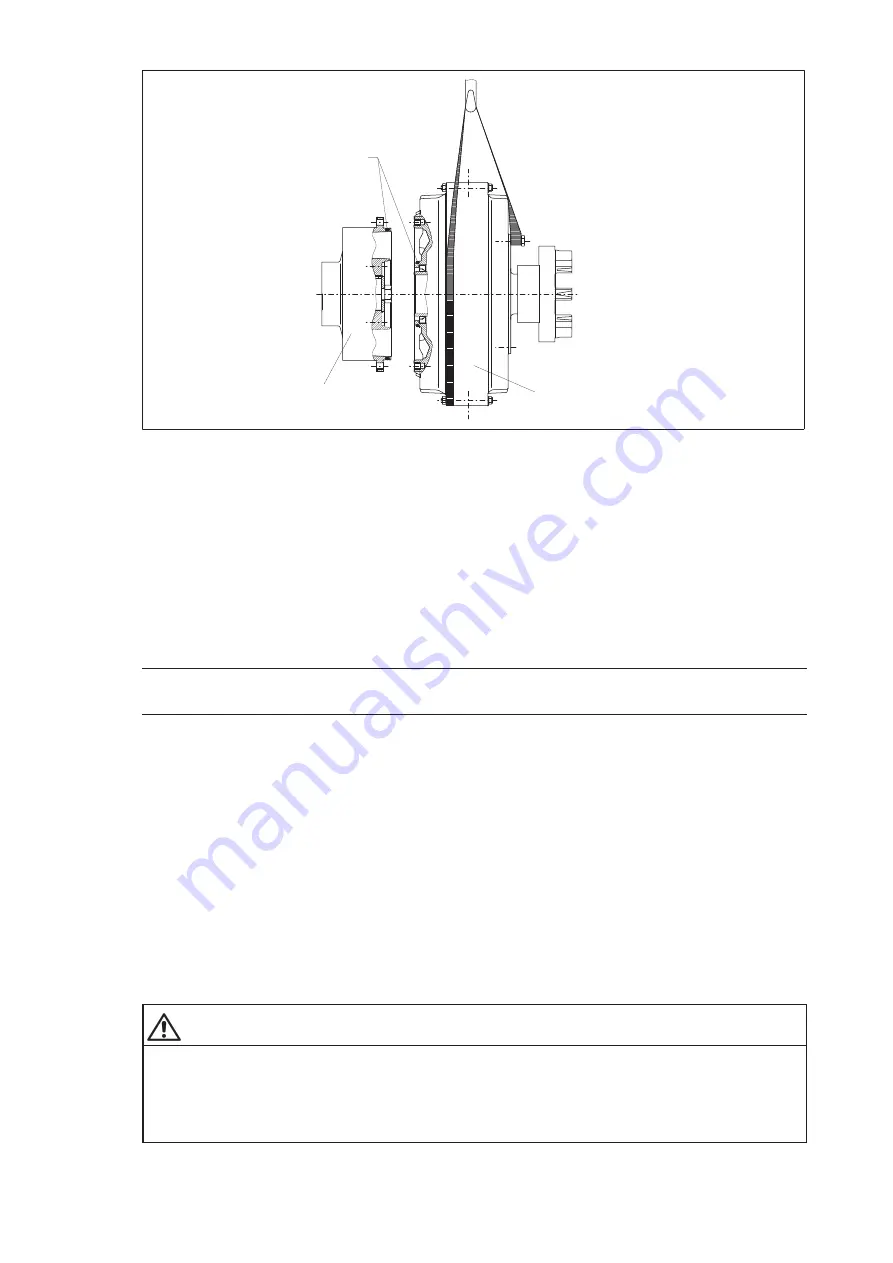
Fig. 8:
Fitting the coupling parts
1) Orings
2) Hubcarrier part (120)
3) Main coupling
•
Before the main coupling is fitted to the hubcarrier part (120) by its flange, any dirt must be removed
from the interior of the hubcarrier part (120) and the corresponding area of the main coupling.
•
Insert the Orings (117, 138), lightly greased, into their mounting grooves.
Note
The sealing and flange surfaces must be clean and undamaged.
To attach the main coupling to the hubcarrier part (120), the main coupling must be suspended in suitable
lifting gear to ensure as coaxial and as straight a positioning on the centring shoulder of the hubcarrier
part (120) as possible.
When flangefitting, care must be taken that the Orings (117, 138) and the sealing surfaces are not
damaged. The flange may be attached by means of the screws (139). Care must be taken to ensure that
the flange surfaces fit closely (for tightening torque of screws, see item 6.6).
•
On part 1 (1) the flexible elements (12) which have been removed must be refitted.
It must be ensured that the flexible elements (12) are of identical size and have identical markings.
The coupling parts must be only at a maximum temperature of + 80 °C.
•
Move together the machines to be coupled.
Dimension "S" must be adhered to. The tightening torques of the bolts parts 13 and 139 are to be checked
(for tightening torques and distance dimension "S", see item 6.6 and section 1).
WARNING
Risk of serious injury through flying fragments
Risk of serious injury through flying fragments and/or attachment of parts with important axial forces or
bending moments acting on the coupling housing.
Before fitting components causing axial forces or bending moments in the coupling, Flender must be
consulted.
Summary of Contents for FLENDER FLUDEX FNA
Page 2: ......


