Document No. 545-433
Installation Instructions
Rev. 4, September, 2002
Information in this publication is based on current specifications. The company reserves the right to make changes in specifications and
models as design improvements are introduced. Other product of company names mentioned herein may be the trademarks of their
respective owners. © 2002 Siemens Building Technologies, Inc.
Siemens Building Technologies, Inc.
1000 Deerfield Parkway
Buffalo Grove, IL 60089-4513
USA
Your feedback is important to us. If you have
comments about this document, please send
them to technical.editor@sbt.siemens.com
Document No. 545-433
Printed in the U.S.A.
Page 2 of 2
FLN0012R1
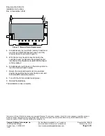
Figure 3. Memory Board Replacement.
4. Simultaneously pry open both memory board card
ejectors and carefully slide the board out of the
memory board cover slots (Figure 3).
5. With the memory board connector facing the
controller board, gently slide the upgrade board
into the memory board cover slots until the board
is firmly seated.
6. Simultaneously push down on the card ejectors to
lock the memory board in place.
7. Return the controller board to its fully installed
position by pushing the memory board cover until
both standoffs snap into position.
8. Turn ON the FLN controller board power.
9. Reload the database.
The installation is now complete.


