
Siemens Industry, Inc.
Building Technologies Division
Florham Park, NJ
P/N 315-049103-6
INSTALLATION INSTRUCTIONS
Model FS-RD2/-R
REMOTE LCD ANNUNCIATOR
The FS-RD2 Remote LCD Annunciator is an optional accessory for the FS-250 Fire Alarm System Control
Panel. The FS-RD2 is black and the FS-RD2-R is red. The FS-RD2/-R provides a 4x20 character LCD display
along with the system status LEDs that display the event status of the system. The enable keyswitch allows
system reset, trouble silence/acknowledge, alarm silence and menu access for partial system control. The lamp
test operation is also enabled by the keyswitch and is limited to the annunciator. The annunciator mounts to a
horizontally mounted 6-gang box, 2” deep minimum. The FS-RD-SB/-R Surface Backbox may be used for
surface mounting. The FS-RD-SB is black and the FS-RD-SB-R is red.
PARTS SUPPLIED
1
FS-RD2/-R Remote LCD Annunciator
4 Mounting
Screws
1 Instruction
Sheet
1 Operating
Instructions
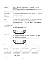
BUTTON ENABLE
ON
OFF
M2
MENU
M1
M4
ALARM SILENCE
ACKNOWLEDGE
M3
SYSTEM RESET
4-
1/
2"
ALARM
SILENCED
ALARM
PRE-
ALARM
SUP
TROUBLE
POWER
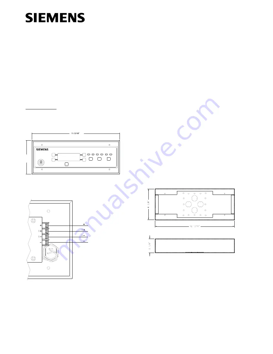
FS-RD2/-R DIMENSIONS
FS-RD2/-R WIRING
Power Limited and Supervised
Step 1.) Installation is to be done by qualified personnel who
have thoroughly read and understood this instruction
sheet.
Step 2.) Disconnect BATTERY and AC prior to working on
equipment.
Step 3.) Mount 6-gang backbox horizontally as required.
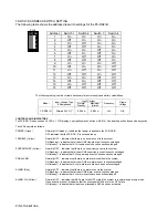
Step 4.) Set dip switch for proper remote address (see page 2).
Step 5.) Attach conduit and run wires as required.
Step 6.) Connect IN wires from fire alarm system control unit or
previous remote as required.
Step 7.) Connect OUT wires to next remote or 120 ohm E.O.L.
Resistor Assembly (P/N 140-050008-1), if last remote.
Step 8.) Attach unit to backbox, using four mounting screws.
Step 9.) Apply power to system.
Step 10.) Check for proper operation of functions.
FS-RD-SB/-R DIMENSIONS
Notes:
1.)
Units to be installed in accordance with all local codes.
2.)
T-Tapping is not allowed! Communication wiring must
be daisy chained from remote to remote.
3.)
Terminal block will accept a maximum of 12 AWG
wiring and minimum of 18 AWG.
4.)
Use twisted pair cable with a characteristic impedance
of approximately 120 ohms. 4000 feet maximum
distance from panel to last remote.
Cable for power (+ & -)
and twisted pair cable for
data (X+ & X-) from panel
or previous remote and to
next remote or 120 ohm
E.O.L. Resistor Assembly
(P/N 140-050008-1) on the
last remote.
Summary of Contents for FS-RD2
Page 4: ...P N 315 049103 6 ...


