Mounting and installation of the compact control panels
Installing the fiber optic cable network module
5
140 | 354
Building Technologies
008851_s_en_--
Fire Safety
2016-01-27
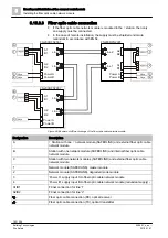
5.15.3.3 Fiber optic cable connection
● If the fiber optic cable network module is mounted in the ↑ station, then only
one supply must be connected.
● In the case of remote installation, the supply must be shielded and made
redundant in accordance with EN 54.
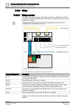
Figure 68: Example of different wirings of the fiber optic cable network module
Designation
Description
A
↑ Station with one ↑ network module (SAFEDLINK) and external fiber optic cable
network module
B
Station with one network module (SAFEDLINK) and internal fiber optic cable
network module
C
Station with two network modules (SAFEDLINK) and external fiber optic cable
network module
1
Network module (SAFEDLINK), master module
2
Network module (SAFEDLINK), degraded mode module
3
'Power A', supply input A to fiber optic cable network module
4
'Power B', supply input B to fiber optic cable network module (redundant supply)
1
A1/B1
FCnet connection for line '1'
A2/B2
FCnet connection for line '2'
Fiber optic cable connection (RX), optical receiver
Fiber optic cable connection (TX), optical transmitter
FN2006/FN2007
FN2006/FN2007
FN2006/FN2007
Line 1
Line 2
A1
B1
A2
B2
A1
B1
A2
B2
A
1
B
1
A2
B2
A1
B1
A2
B2
A1
B1
C
1
2
Vsys
Vsys
3
4
Vsys
3
Vsys
Vsys
3
4
Line 2
Line 1
Line 1
Line 2
Power A
Power B
Power A
Power B
Power A
Power B
A1
B1
A2
B2
A1
B1
A2
B2
A2
B2
A1
B1


