Mounting and installation of the compact control panels
Ethernet switch FN2008 and safety module FN2009
5
259 | 354
Building Technologies
008851_s_en_--
Fire Safety
2016-01-27
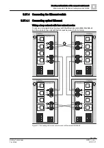
1 Station or empty housing
2 FN2009-A1 Ethernet connection, internal
3 FN2009-A1 Ethernet connection, external
4 Supply connection
5 Ethernet connections switch FN2008-A1
6 Ferrite core for LAN cable
7 Ferrite core for supply cable
Mounting
1. Install the ferrite cores on each supply terminal connection and each LAN cable
plug connection.
2. Loop each connection cable to the plug or connection end with one wind
around the ferrite core.
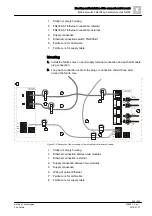
Figure 139: Example of the mounting of two modules in the same housing
1 Station or empty housing
2 Ethernet connection between two modules
3 Ethernet connection, external
4 Supply connection between two modules
5 Supply connection
6 Wiring of optical Ethernet
7 Ferrite core for LAN cable
8 Ferrite core for supply cable
P5
P6
RX
TX
RX
TX
P1
P2
P3
P4
1
P1
P2
L1+
L2+
M1
M2
L1+
L2+
M1
M2
5
4
7
2
3
6
7
8
8


