Mounting and installation of fire terminal (Touch)
Setup of fire terminal (Touch) FT2080
7
330 | 354
Building Technologies
008851_s_en_--
Fire Safety
2016-01-27
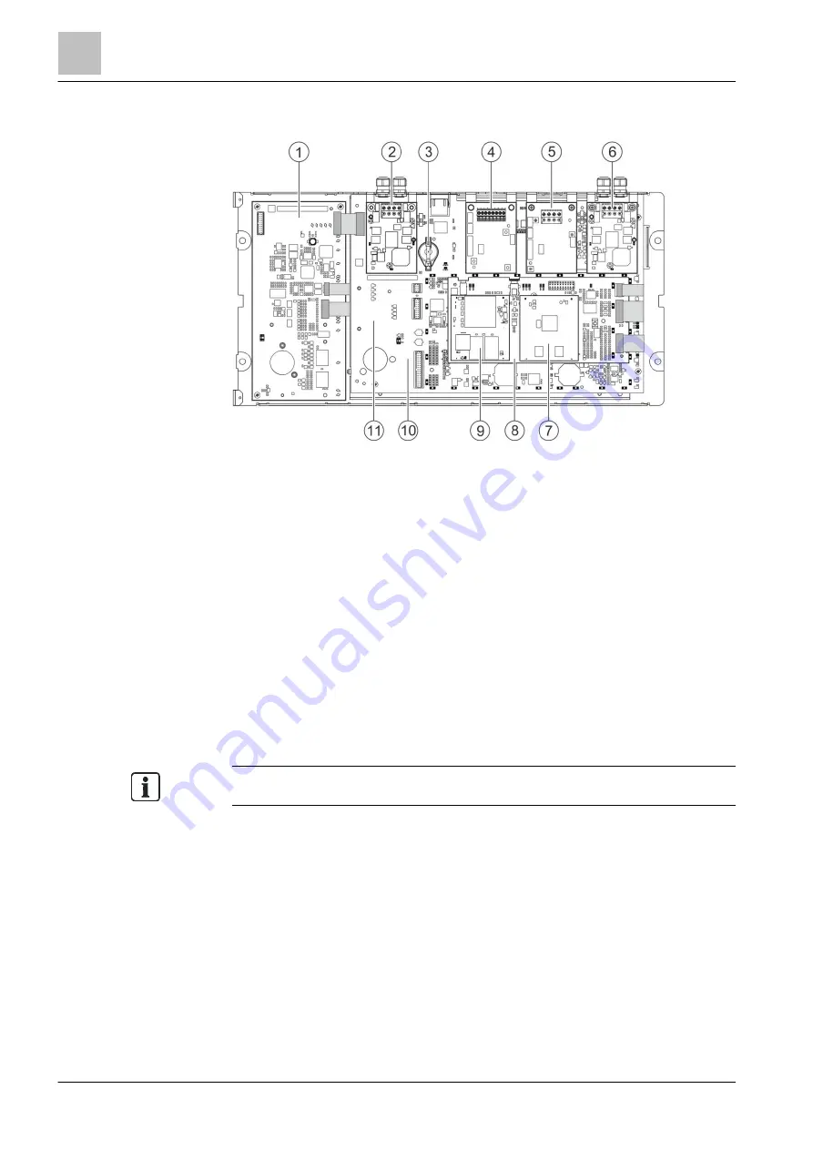
Arrangement of components
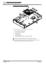
Figure 187: Components on the fire terminal (Touch) FT2080, without cover cap
1 Front indicator (Touch) FTO2010
2 Main network module (SAFEDLINK) on X13, optional
3 License key, optional
4 Slot 1 [SER_OPT1] for the first serial module at X14, optional
5 Slot 2 [SER_OPT2] for the second serial module at X19, optional
6 Degraded mode network module (SAFEDLINK) on X12, optional
7 CPU module (CORVUS) FCC2009
8 Carrier for CPU modules FTO2014
9 CPU module (MPC8248) FCC2006
10 PMI & mainboard FCM2027
11 Slot X11 for serial module. Not required for FT2080
Both slots X14 and X19 can hold the RS232 or RS485 serial module.

