Add-on modules
U41126-J-Z156-1-74
English - 11
Add-on modules
!
For all steps described in this chapter exit the suspend mode before switching off the
device and then pull the power plug out of the power outlet!
Even when you have run down the device, parts of the device (e. g. memory modules,
AGP and PCI extension boards) are still energized.
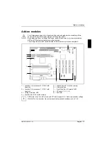
The voltage indicator LED shows whether the main-memory slots are energized.
AG
P
PC
I 5
PC
I 2
PC
I 1
PC
I 3
PC
I 4
0
1
1
2
3
6
7
4
5
8
9
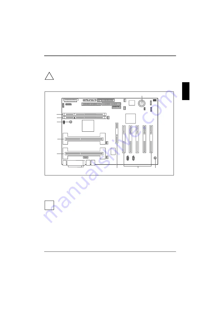
1 = Location 1 for processor 0 / CPU 0 with
heat sink
2 = Location 2 for processor 1 / CPU 1 with
heat sink
3 = Voltage indicator LED
4 = Location bank 0 for main memory
5 = Location bank 1 for main memory
6 = Lithium battery
7 = Front Side Bus - Mismatch LED
8 = PCI slots 1, 2, 3, 4, 5
9 = AGP slot
i
AGP slots in the 1x and 2x mode and PCI slots support 3.3 V main and auxiliary voltage.
With AGP in the 4x mode, the system board automatically switches over to 1.5 V.


