background image

8/10

03.09.1999

4 319 2615 0 e

Siemens Building Technologies / Landis & Staefa Division

de

Kabelbezeichnungen

Anschluss-
kabel

Ader-
beschriftung

Bezeichnung

Farbe

LG-Klemmen-
Code

Antriebe

1

System Potential AC 24 V

rot

G

AC 24 V

2

Systemnull

schwarz

G0

6

Stellsignal öffnen AC 0 V (6-2)

violett

Y1

7

Stellsignal schliessen AC 0 V (7-2)

orange

Y2

8

Stellsignal DC 0...10 V (8-2)

grau

Y

9

Stellungsanzeige DC 0...10 V (9-2)

rosa

U

Antriebe

3

Phase AC 230 V

braun

L

AC 230 V

4

Nullleiter

blau

N

Hilfsschalter

S1

Schalter A  Eingang

grau/rot

Q11

S2

Schalter A  Ruhekontakt

grau/blau

Q12

S3

Schalter A  Schliesskontakt

grau/rosa

Q14

S4

Schalter B  Eingang

schwarz/rot

Q21

S5

Schalter B  Ruhekontakt

schwarz/blau

Q22

S6

Schalter B  Schliesskontakt

schwarz/rosa

Q24

Stellungsgeber

P1

Potentiometer 0...100 % (P1-P2)

weiss/rot

a

P2

Potentiometer  Abgriff

weiss/blau

b

P3

Potentiometer 100...0 % (P3-P2)

weiss/rosa

c

en

Wire Descriptions

Connecting
Cable

Core Label-
ing

Description

Color

LG-Terminal
Code

AC 24 V

1

System potential AC 24 V

red

G

Actuators

2

System neutral

black

G0

6

Actuating signal open AC 0 V (6-2)

purple

Y1

7

Actuating signal close AC 0 V (7-2)

orange

Y2

8

Actuating signal DC 0...10 V (8-2)

gray

Y

9

Position indication DC 0...10 V (9-2)

pink

U

AC 230V

3

Line AC 230 V

brown

L

Actuators

4

Neutral

blue

N

Auxiliary switch

S1

Switch A  Input

gray/red

Q11

S2

Switch A  Normally closed contact

gray/blue

Q12

S3

Switch A  Normally open contact

gray/pink

Q14

S4

Switch B  Input

black/red

Q21

S5

Switch B  Normally closed contact

black/blue

Q22

S6

Switch B  Normally open contact

black/pink

Q24

Position

P1

Potentiometer 0...100 % (P1-P2)

white/red

a

indicator

P2

Potentiometer  wiper

white/blue

b

P3

Potentiometer 100...0 % (P3-P2)

white/pink

c

fr

Désignation des câbles

Câbles de
raccordement

Designation
conducteurs

Signification

Couleurs

Code de
bornes LG

servo-moteurs

1

potentiel du système AC 24 V

rouge

G

AC 24 V

2

zéro du système AC 24 V

noir

G0

6

signal de commande ouvrir AC 0 V (6-2)

violet

Y1

7

signal de commande fermer AC 0 V (7-2)

orange

Y2

8

signal de commande DC 0...10 V (8-2)

gris

Y

9

signal de position DC 0...10 V (9-2)

rose

U

servo-moteurs

3

phase AC 230 V

brun

L

AC 230V

4

neutre

bleu

N

commutateurs

S1

commutateur A entrée

gris/rouge

Q11

auxiliaires

S2

commutateur A  contact de repos

gris/bleu

Q12

S3

commutateur A  contact de travail

gris/rose

Q14

S4

commutateur B  entrée

noir/rouge

Q21

S5

commutateur B  contact de repos

noir/bleu

Q22

S6

commutateur B  contact de travail

noir/rose

Q24

indicateur de

P1

potentiomètre 0...100 % (P1-P2)

blanc/rouge

a

position

P2

potentiomètre  curseur

blanc/bleu

b

P3

potentiomètre 100...0 % (P3-P2)

blanc/rose

c

Summary of Contents for GCA 1 Series

Page 1: ... 1 90 IP65 M4613 4 319 2615 0 de Montageanleitung Drehantrieb mit Federrücklauf en Mounting instructions Rotary type spring return actuator fr Instructions de montage Servo moteur à action angulaire avec ressort de rappel sv Monteringsinstruktion Spjällställdon med vridande rörelse och fjäderåtergång nl Montage aanwijzing Luchtklepservomotor voor veertuggang it Istruzioni di montaggio Servocomando...

Page 2: ...ing 5 Terugloop Elektrisch of mechanisch Bekabeling en inbedrijfstelling Raadpleeg de installatie documentatie en het apparatenblad voor de servomotor Conserve estas instrucciones con el actuador o con la documentación de la instalación La conexión eléctrica del actuador a 230 V CA debe hacerse solamente por personal autorizado Atención el actuador no debe ser abierto Compresión del muelle Compres...

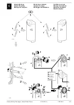
Page 3: ...ontering av adapter Apadper montage Montaggio dell adattatore Sovittimen asennus Montaje del adaptador Montering af adapter Montaż adaptera 90 90 2 2 4613Z06 5 90 6 5 20 mm 77 mm 77 mm 4 3 3 7 d b a c 6 d a c 4613Z19 4613Z05 4613Z03 4613Z02 5 4 b e 0 click 4613Z97 Montagemarkierung Mounting mark Marquage de positionnement Oznaczenie montażowe ...

Page 4: ...ääntökulman rajoitus Límites del ángulo de rotación Begrænsning af drejevinkel Ograniczenie kąta obrotu a d 4613Z13 2 1 c 3 0 5 10 15 0 5 90 b E Montage auf Klappenachse Shaft Mounting Montage sur l axe des volets Montering på spjällaxel Montage op de luchtklepas Montaggio all asse della serranda Asennus pellin akseliin Montaje sobre el eje de las comp Montering på spjældaksel Montaż na przepustni...

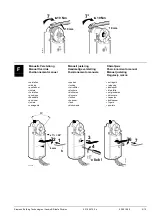
Page 5: ...icionamiento manual Manuel justering Regulacja ręczna verstellen sperren entriegeln winding locking releasing positionner verrouiller débloquer justera blockera återställa verstellen blokkeren ontgrendelen posizione bloccare sbloccare käsisäätö lukitus vapautus psicionar boquear dsbloquear justere låse frigøre naciągania blokowania powrotu 4613Z12 GEAR TRAIN LOCK PIN GEAR TRAIN LOCK PIN GEAR TRAIN...

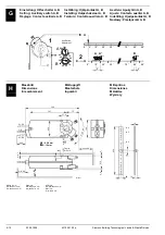
Page 6: ...70 60 50 B 90 Aux Switch Adjustment 20 30 40 10 20 40 A 70 90 0 5 M A B 5 0 10 20 30 70 80 90 0 10 20 30 70 80 90 A 5 2 M A B 4613Z28 2 1 H Massbild Dimensions Encombrement Måttuppgift Maatschets Ingombri Mittapiirros Dimensiones Målskitse Wymiary min 7 300 73 85 8 m a x 9 5 900 min 100 min 60 min 200 20 13 13 230 1 5 4 2 67 5 3 4613M01 100 27 6 ø 5 7 15 197 Ø 8 25 6 mm o o o o 6 18 mm max 20 P1 P...

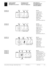
Page 7: ... rien Tvåläges styrning Tweepuntsbesturing Comando a 2 posizioni Kaksipisteohjaus Control a 2 puntos On off styring Sygnał sterujący dwupołożeniowy GCA 131 1E GCA 135 1E 4627G01 A 100 0 Y2 AC 0 V 0 1000 Ω AC 24 V 230 V 6 2 A GCA13 a G Q12 Q14 Q24 Q22 1 S2 S3 S5 S6 7 P3 S1 S4 Q11 Q21 B M Y1 b c 6 P1 P2 G0 2 AC 24 V AC 24 V Dreipunkt Steuerung Three position control Commande 3 points Treläges styrni...

Page 8: ...C 0 10 V 9 2 pink U AC 230V 3 Line AC 230 V brown L Actuators 4 Neutral blue N Auxiliary switch S1 Switch A Input gray red Q11 S2 Switch A Normally closed contact gray blue Q12 S3 Switch A Normally open contact gray pink Q14 S4 Switch B Input black red Q21 S5 Switch B Normally closed contact black blue Q22 S6 Switch B Normally open contact black pink Q24 Position P1 Potentiometer 0 100 P1 P2 white...

Page 9: ...erujący 0 10 V DC Y G0 szary Y 9 Wskazanie położenia 0 10 V DC U G0 różowy U Siłowniki 3 Faza 230 V AC brązowy L 230 V AC 4 Zero niebieski N Przełączniki S1 Przełącznik A wejście szary czerw Q11 pomocnicze S2 Przełącznik A styk bierny szary nieb Q12 S3 Przełącznik A styk czynny szary różowy Q14 S4 Przełącznik B wejście czarny czerw Q21 S5 Przełącznik B styk bierny czarny nieb Q22 S6 Przełącznik B ...

Page 10: ...10 10 03 09 1999 4 319 2615 0 e Siemens Building Technologies Landis Staefa Division ã 1999 Siemens Building Technologies Ltd ...

Reviews: