12 / 14
Siemens
A6V10631832_en--_b
Building Technologies
2016-01-29
Register 769 “Status”
Status
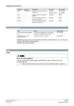
Bit 00
1 = Local override
Bit 06
1 = Adaption done
Bit 01
1 = Backup mode active
Bit 07
1 = Adaption in progress
Bit 02
1 = Sensor comm. fault
Bit 08
1 = Adaption error
Bit 03
1 = Sensor tubes crossed
Bit 09
1 = Selftest failed
Bit 04
1 = Device jammed
Bit 10
1 = Selftest passed
Bit 05
1 = Nom. lifetime exceeded
Bit 11
1 = Invalid configuration
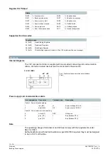
Supported function codes
Function codes
03 (0x03)
Read Holding Registers
04 (0x04)
Read Input Registers
06 (0x06) Write Single Register
16 (0x10)
Write Multiple registers (Limitation: Max. 120 registers within one message)
Diagrams
Internal diagrams
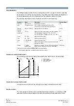
The VAV compact controller is supplied with two prewired connecting and communication
cables. All interconnected devices must be connected to the same G0.
G..B181.1E/MO
Tool = Configuration and maintenance interface
(7-pin)
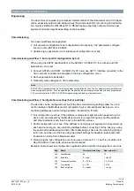
Power supply and communication cables
Core designation
Core color
Terminal code
Description
Cable 1: Power / black sheathing
1
red (RD)
G
System voltage AC 24 V
2
black (BK)
G0
System neutral AC 24 V
Cable 2: Communication / blue sheathing
6
violet (VT)
REF
Reference
8
grey (GY)
+
Bus (Modbus RTU)
9
pink (PK)
-
Bus (Modbus RTU)
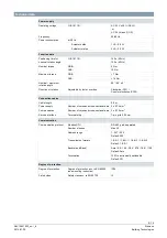
Note
The operating voltage at terminals G and G0 must comply with the requirements under
SELV or PELV.
Safety transformers with twofold insulation as per EN 61558 required; they must be designed
to be on 100 % of the time.


