Cerberus Division
Product description
e1476.doc
Data and design subject to change without notice. Supply subject to availability
© Copyright by Siemens Building Technologies AG Cerberus Division, CH-8708 Männedorf, Switzerland 1999
03.99
3 [14]
2
Product description
2.1 The CPU board
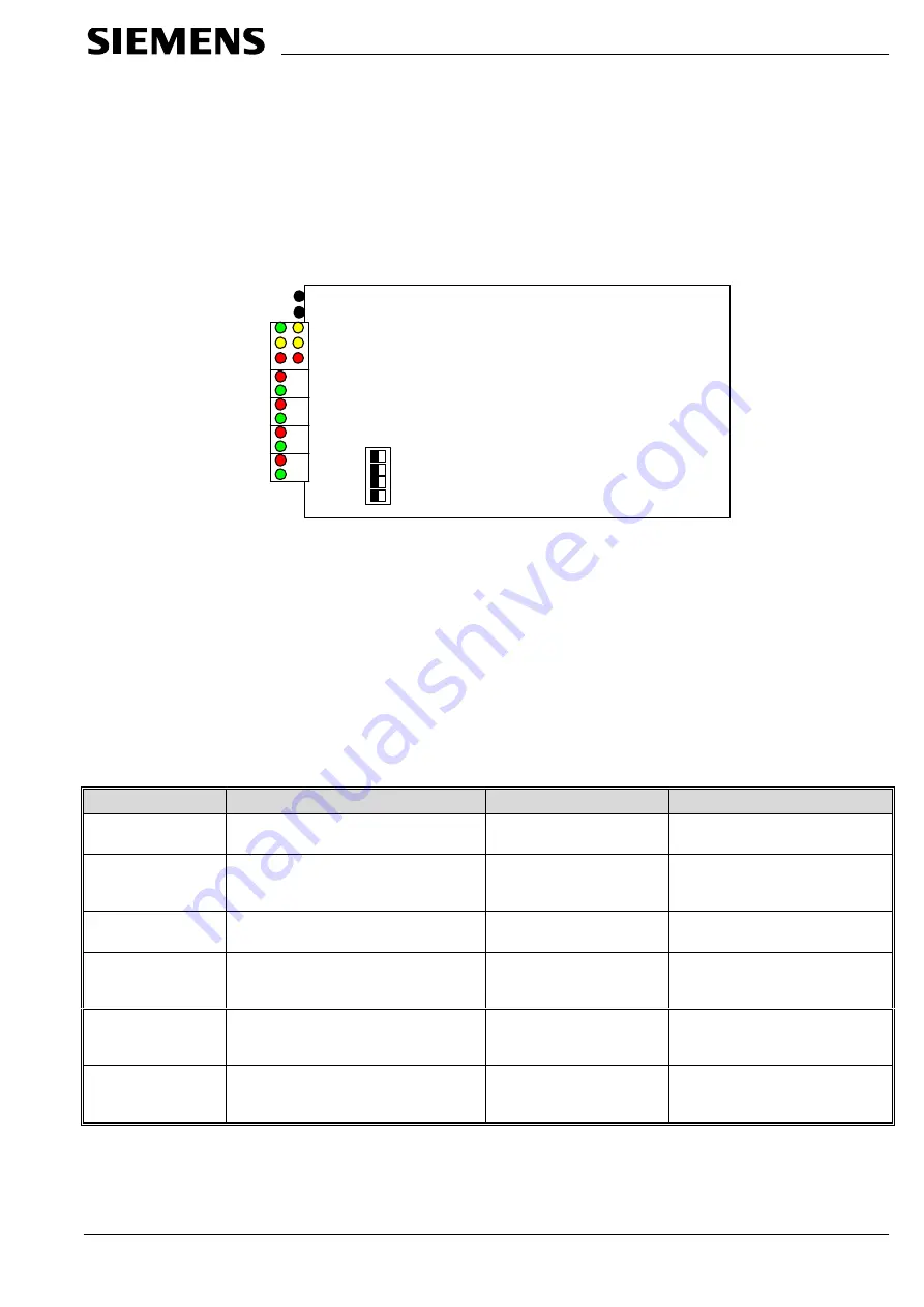
The CPU board is the main board (CD98600).
Fig. 2-1 - The CPU board
On this board there are:
•
the CPU, RAM, UARTs and other electronic components
•
four dip switch blocks (SW1 - SW4), used only for the board factory setup
•
one reset push-button, used to reset the board
•
one service push-button, to send the service signal to the Neuron Chip
•
four sets of two LEDs (TX green and RX red); these LEDs show the status of
UARTs RX/TX lines
•
six LEDs (LD1-LD6 green, yellow, and red) used for diagnostic purposes.
The six diagnostic LEDs marked LD1, LD2 and LD3 have the following meaning:
ON
OFF
Blinking
LD1 Vitality
(green)
Firmware vitality trouble
Firmware vitality trouble
OK
LD2 Service
Not used
(yellow)
LD3 Identification
(yellow)
GW-23 not yet identified from
control center (GW-10).
OK
-
LD4
Download
(yellow)
-
OK
Download in progress
LD5
RAM error
(red)
Internal diagnostic error
OK
Internal diagnostic error
LD6
Download error
(red)
The GW-23 cannot proceed. An error
occurred in the download
OK
The GW-23 cannot proceed.
An error occurred in the download
Fig. 2-2 - The I/O board
All dip-switches must be left to OFF.
The board also includes some jumpers: do not modify the factory setting.
LD1 Vitality
LD3 Identification
LD5 RAM error
RX1
TX1
RX2
TX2
RX3
TX3
RX4
TX4
SW1
SW2
SW3
SW4
Reset
Reset


