


Turn off and lock out all power supplying this device before
working on this device.
Replace all covers before power supplying this device is
turned on.
Couper l'alimentation de l'appareil et barrer avant de
travailler.
Remplacez touts les couverts avant que
l'approvisionnement de pouvoir soit alimenté.
Tensión peligrosa.
Puede causar la muerte o lesiones graves.
Tension dangereuse.
Danger de mort ou risque de blessures graves.
Hazardous Voltage.
Will cause death or serious injury.
Desenergice totalmente antes de instalar o darle servicio.
Reemplace todas las barreras y cubiertas antes de
energizar el interruptor.
2 / 10 (English)
I.L. No. 508533A00
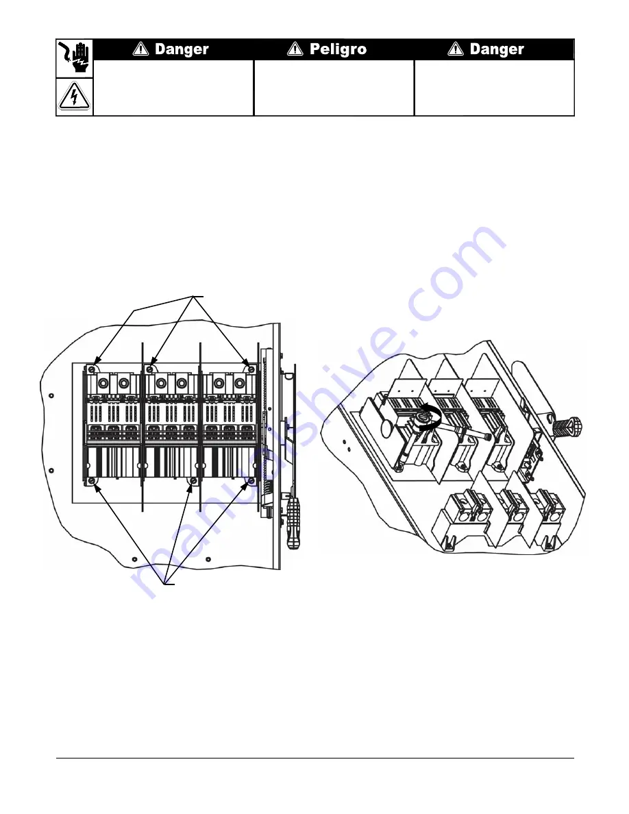
1.
Prepare switch for mechanism replacement.
Turn OFF and lock out all power supplying this device before working on the device.
Turn OFF the switch
Verify that NO voltage is present at the wire grips.
Remove any installed fuses (Fusible Switches).
Rotate line shields for access to line base mounting screw as shown in Fig’s 1 & 2.
Remove all conductors from the line base.
2.
Remove the Line Base Mounting Screws as shown in Fig. 2. Keep hardware for re-installation.
(View shows line shield rotated.)
Fig. 1
Line Base
Mounting Screw
Line Base
Mounting Screw
Fig. 2


