Parameter reference
8.6 Setup (2.)
HydroRanger 200 HMI
214
Operating Instructions, 06/2018, A5E36281317-AC
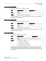
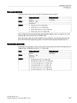
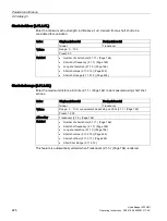
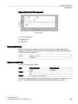
Exponent (2.10.2.3.)
Establishes the number of flow units required to increment the Flow Sampler (the device
connected to the relay set to Relay Function (2.8.1.4.) (Page 195) = Flow Sampler), in
conjunction with Mantissa (2.10.2.2.) (Page 213).
Index
Single-point model
Dual-point model
Global
Transducer
Values
Range: -3 to +7 (integers only)
Preset: 0
Related
•
Sensor mode (2.1.3.) (Page 163)
•
Relay function (2.8.1.4.) (Page 195)
•
Primary measuring device (2.13.2.) (Page 240)
•
Flow exponent (2.13.4.1) (Page 241)
•
PMD dimensions (2.13.5.) (Page 246)
•
Maximum head (2.13.4.2.) (Page 243)
•
Maximum flow (2.13.4.3.) (Page 243)
•
Zero head (2.13.4.5.) (Page 244)
•
Flow time units (2.13.4.4.) (Page 244)
•
Flowrate decimal (2.13.4.6.) (Page 245)
•
Head 1 (2.13.6.1.1.) (Page 247)
•
Flow 1 (2.13.6.1.2.) (Page 248)
•
Low flow cutoff (2.13.4.8.) (Page 246)
•
Auto zero head (2.13.3.) (Page 240)
•
Mantissa (2.10.2.2.) (Page 213)
This parameter is relevant only if Operation is set to OCM [Sensor Mode (2.1.3.) (Page 163)
= Flow rate in open channel].
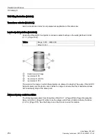
Enter the exponent (Z) for the mantissa (Y) in the formula:
Flow Sampler Increment = Y x 10
Z
Flow units
Summary of Contents for HydroRanger 200 HMI
Page 2: ......
Page 24: ...Safety notes HydroRanger 200 HMI 22 Operating Instructions 06 2018 A5E36281317 AC ...
Page 354: ...Updating software HydroRanger 200 HMI 352 Operating Instructions 06 2018 A5E36281317 AC ...
Page 362: ......
Page 403: ......

