2
Chapter 1
Introduction
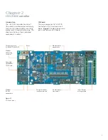
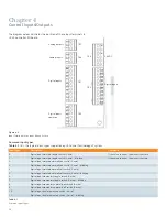
Figure 1.2
i-3 Controller Front View
Front Panel Overview
Overview
The purpose of this manual is to help users
develop safe and efficient procedures for
the installation, operation and maintenance
of the i-3 V2 I/O Modbus Controller.
The i-3 V2 I/O Controller is used to control
the operation of P1 Series with i-3 Control
Technology V2 Panel. The controller directs
SIPODs (Remotely Operated Contactors)
to switch ON/OFF. It also monitors the
contact status up to 42 branch circuits.
The i-3 V2 I/O Controller enables the P1
lighting panel to operate as a slave panel
to accept dry contact or wet digital inputs
and analog inputs or commands through
communications network by a Building
Automation System. It provides up to 20
two-wire dry or wet contact inputs and
two analog inputs which can be used to
control up to 42 outputs.
All SIPOD ON
P1 Box
Data Rail
Ribbon
Cable
BQD
SIPOD
Data Rail
Ribbon
Cable
Input
Terminals
I/O Board
PC or BAS
(Modbus
Interface)
RS485 to
RS232
converter
Up to 21
Up to 21
Power
Supply
Figure 1.1
Single Slave Panel System Overview
All SIPOD OFF
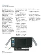
Normal
operation
Three way switch
All ON-AUTO-ALL OFF
Modbus
addressing switches
RS485 connections
Fuse
Power switch
Note:
The switch must
be on the “AUTO”
position during
commissioning and
normal operation.
Reset
Connector
for Modbus
TCP/IP card
Ribbon
cable
Summary of Contents for i-3
Page 1: ...3 User Guide www usa siemens com i 3 i 3 V2 I O Controller Modbus ...
Page 54: ...52 Appendix E USB to RS485 Converter Driver Software Installation Instructions ...
Page 57: ...55 Appendix F Recommended Input Devices ...
Page 58: ...56 Appendix F Recommended Input Devices ...
Page 59: ...57 Appendix F Recommended Input Devices ...
Page 60: ...58 Appendix F Recommended Input Devices ...
Page 61: ...59 Appendix F Recommended Input Devices ...
Page 62: ...60 Appendix F Recommended Input Devices ...
Page 63: ...61 Appendix F Recommended Input Devices ...
Page 64: ...62 Appendix F Recommended Input Devices ...
Page 65: ...63 Appendix F Recommended Input Devices ...
Page 66: ...64 Appendix F Recommended Input Devices ...
Page 67: ...65 Appendix F Recommended Input Devices ...
Page 68: ...66 Appendix F Recommended Input Devices ...
Page 69: ...67 Appendix F Recommended Input Devices ...
Page 70: ...68 Appendix F Recommended Input Devices ...
Page 71: ...69 Appendix F Recommended Input Devices ...
Page 72: ...70 Appendix F Recommended Input Devices ...
Page 73: ...71 Appendix F Recommended Input Devices ...
Page 74: ...72 Appendix F Recommended Input Devices ...
Page 75: ...73 Appendix G Common Networking Setups ...
Page 76: ...74 Appendix G Common Networking Setups ...
Page 78: ...76 Notes ...
Page 79: ......


