10
Chapter 3
Installation
Wiring Installation
For electrical load wiring information,
refer to Breaker rating label located
on the face of the breaker.
Ground terminations to the enclosure
should be made after the P1 interior is
installed in the enclosure to prevent
physical interference with wires.
Configuring i-3 V2 controller
For complete detail on i-3 V2 controller
configuration, refer to i-3 V2 I/O Controller –
Modbus, PN LVIN-MODCO-0212; or for
System Controller, refer to the i-3 System
Controller User Guide, P/N LCIM-SYCON-0212.
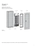
Deadfront installation
Prior to completing the installation
of panel deadfront and trim, carefully
review the Inspection section in
Chapter 4 – Inspection and Testing.
1. Be sure the deadfront is installed prior
to closing of the panel.
2. Be sure all breakers extend properly
through the deadfront openings and
any provisions or spaces are properly
covered with deadfront fillers. Normal
unit space opening may use Siemens
QF3 filler plates.
Trim/Door installation
For trim/door installation, refer to “Trim
Mounting Instructions,” which is shipped
with the trim.
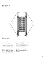
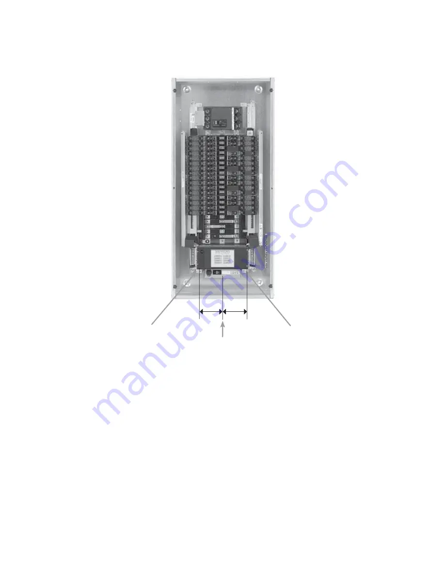
Communications wiring access
Inputs wiring access
Center line
4.2”
4.2”
Figure 3-4

