16
Chapter 6
System components
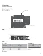
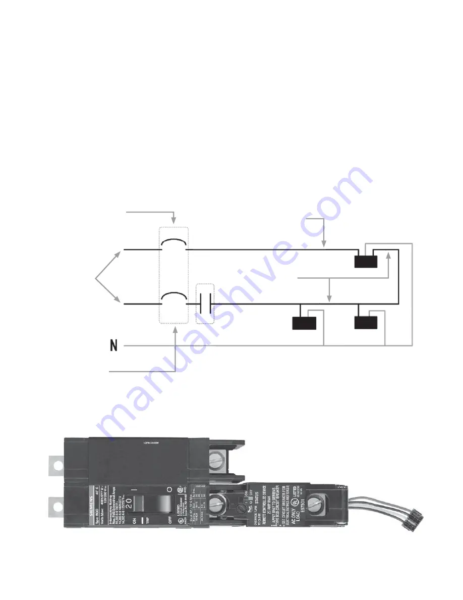
Figure 6.8
Figure 6.9
Emergency lighting circuits application
The i-3 Technology V2 System offers an
option to control emergency lighting
circuits. This option meets the
requirements of the National Electrical
Code, 700.12(F).
For this application i-3 V2 utilizes a
standard two pole BQD breaker coupled
with a standard one-pole SIPOD. The
assembly is installed in a especially factory
modified P1 panelboard.
Note: This is not a field modification
option. The i-3 V2 system with this option
should be ordered with this modification.
An i-3 V2 system with emergency lighting
circuits can have 2, 4, 6, 8, 10 or 12
circuits factory modified for this application.
BQD breaker
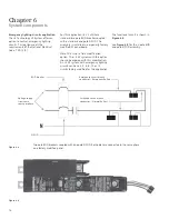
The functional circuit is shown in
Figure 6.8
.
See
Figure 6.9
for the 2-pole BQD –
one-pole SIPOD assembly.
Two pole BDQ breakers coupled with one pole SIPOD. Both poles are connected to the same phase
on a factory modifi ed panel.
SIPOD
Emergency circuit branch
conductor – Emergency Ballast
Switched circuit branch
conductor – Normal Ballast
Voltage supply
from same
source or phase


