32
I-T-E Mechanical Interlock (M15404)
D.
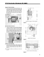
Using tie bar wrench carefully positioned over tie bar
connector, (so as not to damage support tie bar assem-
bly), pull tie bar back in direction of arrow and remove
wood block. With care remove tie bar wrench.
E.
Replace handle if removed.
NOTE: Tab on front of handle must be aligned toward line end.
F
Replace load cover The six #10-32 x 3/4 in. screws must
be installed toward the line side of the circuit breaker. The
two 10-32 x 13/8 in. screws are installed on the load end.
Tighten all load cover screws to 25 in.-lb.
Rocker Arm Mounting
A.
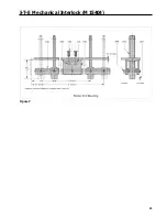
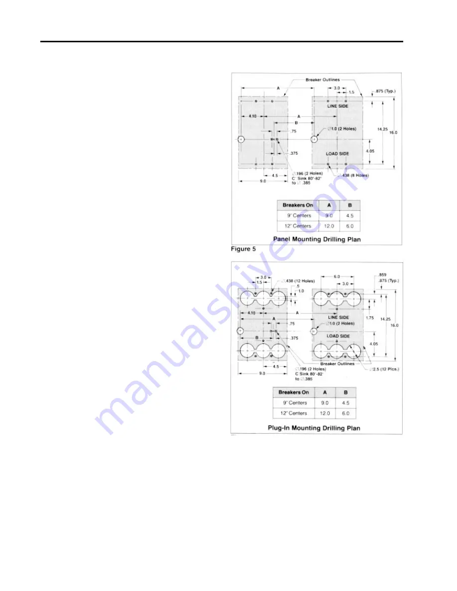
Drill panel as shown for panel mounting (circuit breakers
on 9 or 12 in. centers), (Figure 5). For plug in mounting,
see Figure 6.
B.
Assemble bracket (15) to rear of 10 gage customer panel
using two flat head screws (16), lockwashers (17) and
nuts (18) supplied as shown in Figure 7.
C.
Assemble rocker arm (19) to bracket with rocker arm pin
(20).
NOTE: Heads of rocker arm pin must be on upper side of
assembly and cotter pin (21) on lower side. Insert cotter
pin into hole in rocker arm pin and secure by spreading
ends (Figure 7).
D.
Add circuit breakers (specially prepared) to customer’s
panel for panel mounted or plug-in adapters and circuit
breakers for plug in applications. Refer to installation
instruction supplied with plug-in adapters Catalog PC5662
or PC5663. Carefully position circuit breaker over 1.00 in.
diameter hole in panel so as not to damage protruding
plunger For panel mounted applications use Catalog
MSMN mounting screw kit (part of mechanical interlock
Catalog Ml5404) to fasten circuit breaker to customer’s
panel. Replace terminal shields. Tighten two #8-32 screws
each to 12 in.-lb.
E.
Assemble rocker arm pins through rocker arm and slot in
plunger and insert cotter pin into hole in pin and spread
. ends (Figure 7).
NOTE: Heads of rocker arm pins must be on upper side of
assembly and cotter pins on lower side.
F
With both circuit breakers in OFF position, interlock must
move freely.
G.
With one circuit breaker ON the other circuit breaker
must not close.
H.
Affix labels (22) to front of both circuit breakers as shown
in Figure 1.
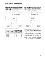
NOTE: Installation of a Mechanical Interlock system prevents
use of internal accessories in the left pole of the circuit
breakers.
Figure 6
Summary of Contents for I-T-E Sensitrip MD Series
Page 2: ......
Page 6: ...4 I T E Sensitrip Digital Circuit Breaker MD and ND Frame Outline Drawings 1 3 Pole ...
Page 8: ...6 MD and ND Frame Trip Adjustments ...
Page 12: ...10 MD and ND Frame Time Current Curve 600 1000A With Short Time Delay Set on Fixed Time ...
Page 13: ...MD and ND Frame Time Current Curve 11 1200A With Short Time Delay Set on Fixed Time ...
Page 14: ...12 MD and ND Frame Time Current Curve 600 100A With Short Time Delay Set on I2 t ...
Page 15: ...MD and ND Frame Time Current Curve 13 1200A With Short Time Delay Set on I2 t ...
Page 16: ...14 MD and ND Frame Time Current Curve 600 100A Without Short Time Settings ...
Page 17: ...MD and ND Frame Time Current Curve 15 1200A Without Short Time Settings ...
Page 18: ...16 MD and ND Frame Time Current Curve Ground Fault Trip Data ...
Page 19: ...MD and ND Frame Time Current Curve 17 Example ...
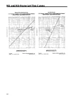
Page 20: ...18 MD and ND Frame Let Thru Curves ...
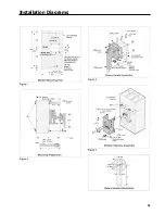
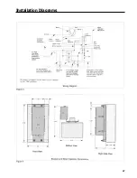
Page 31: ...Installation Diagrams 29 ...
Page 35: ...I T E Mechanical Interlock M15404 33 Figure 7 ...
Page 41: ...Installation Diagrams 39 ...
Page 49: ...Installation Diagrams 47 ...
Page 50: ...48 I T E Panelboard Connecting Straps 1 ...
Page 53: ...Installation Diagrams 51 ...

