40
I-T-E Max-Flex
TM
Flange-Mount Handle Operator
Types 1, 3R, 4, 4X, 12
General Information
The l-T-E Max-Flex Flange-Mount Handle Operator is a flex-
ible cable control device used for the remote switching of a
circuit breaker within an enclosure. The flexible cable is
connected directly to the breaker at one end and to a pre-
assembled switch handle operator at the other end. The
remote operator handle, located on the enclosure flange, is
used to perform mechanical open/close switching opera-
tions. This is accomplished through the flexible control cable
Function
The advanced design concept of the Max-Flex Flange-Mount
Handle Operator provides for greater flexibility when locating
a circuit breaker within an enclosure. The circuit breaker can
be mounted almost anywhere, at any angle and on almost any
convenient surface. The same flexibility applies when locating
the switch handle operator on the flange section of the
enclosure.
Application
The Max-Flex Operator is designed to work with l-T-E circuit
breakers having current ratings through 1200 amperes. The
Max-Flex unit meets all the industrial criteria such as UL and
Automotive Industry Standards.
Design
The new Max-Flex Handle Operator provides maximum flex-
ibility in design and assembly of electrical equipment.
The cable design is flexible and rugged. The flexible cable
comes in standard 4 or 5 foot lengths. However, specific
lengths can be special ordered up to 20 feet.
Operation
When properly installed, the Max-Flex Handle Operator is
used to perform remote switching operations from outside of
the enclosure. Switching is accomplished by pushing the
Max-Flex Handle Operator up for ON and down for OFF. The
mechanical advantage gained with this device simplifies switch-
ing operations when compared with local switching at the
breaker
Interlocking provisions are included and described below. All
switching functions are standard according to accepted
practices.
Unassembled Max-Flex
TM
Flange-Mount Handle Operator
Summary of Contents for I-T-E Sensitrip MD Series
Page 2: ......
Page 6: ...4 I T E Sensitrip Digital Circuit Breaker MD and ND Frame Outline Drawings 1 3 Pole ...
Page 8: ...6 MD and ND Frame Trip Adjustments ...
Page 12: ...10 MD and ND Frame Time Current Curve 600 1000A With Short Time Delay Set on Fixed Time ...
Page 13: ...MD and ND Frame Time Current Curve 11 1200A With Short Time Delay Set on Fixed Time ...
Page 14: ...12 MD and ND Frame Time Current Curve 600 100A With Short Time Delay Set on I2 t ...
Page 15: ...MD and ND Frame Time Current Curve 13 1200A With Short Time Delay Set on I2 t ...
Page 16: ...14 MD and ND Frame Time Current Curve 600 100A Without Short Time Settings ...
Page 17: ...MD and ND Frame Time Current Curve 15 1200A Without Short Time Settings ...
Page 18: ...16 MD and ND Frame Time Current Curve Ground Fault Trip Data ...
Page 19: ...MD and ND Frame Time Current Curve 17 Example ...
Page 20: ...18 MD and ND Frame Let Thru Curves ...
Page 31: ...Installation Diagrams 29 ...
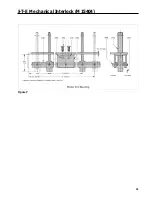
Page 35: ...I T E Mechanical Interlock M15404 33 Figure 7 ...
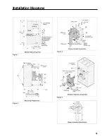
Page 41: ...Installation Diagrams 39 ...
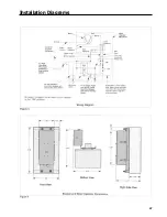
Page 49: ...Installation Diagrams 47 ...
Page 50: ...48 I T E Panelboard Connecting Straps 1 ...
Page 53: ...Installation Diagrams 51 ...


