60
UL Listings and File Numbers
Industry Specifications
AAAA
AAAA
AAAA
AAAA
AAAA
AAAA
AAAA
AAAA
AAA
AAA
AAA
AAA
AAAA
AAAA
AAAA
AAAA
AAAA
AAAA
AAAA
AAAA
A
A
A
A
AAAA
AAAA
AAAA
AAAA
AAAA
AAAA
AAAA
AAAA
AAA
AAA
AAA
AAA
I-T-E Items
UL-489File
Number
CSA Report
Number
Breakers
Terminal Connectors
Plug-ln Connectors
Rear Studs
Accessories
Shunt Trip
Undervoltage Trip
Aux. Switch
Bell Alarm Switch
Enclosures
E10848
E23615 (sp.)
-
-
E69455
E69455
E69455
E69455
E10848
LR57039
LR13077
-
-
LR13077
LR13077
LR13077
LR13077
-
100 Percent Rating Information
MD-Frame MD-Frame breaker types are suitable for continu-
ous operation at 100% of rating only if used in an enclosure or
cubicle space 40.2 x 22.5 x 10.7 in.
The MD-Frame 100 percent rated breaker types SMD6,
SHMD6 and SCMD6 are marked on the breaker label as
follows:
Wire Connectors
Catalog Number
Wire Range
Torque
TA4P500
(4) 250-500 MCM Cu/AI
375 in. Ib.
CCMB00
See instructions
For the correct 90 C wire size use Table 8.1 in UL 489
according to the rating of the breaker.
National Fire Protection Assoc. (National Electrical Code).
Federal Specification C-375B/GEN.
Underwriters Laboratories, Inc. (UL 489).
Canadian Standards Association (C22.2 No. 5).
ND-Frame
ND-Frame breaker types are suitable for continuous opera-
tion at 100% of rating only if used in an enclosure or cubicle
space 60 x 22.5 x 10 in.
The ND-Frame 100 percent rated breaker types SND6,
SHND6 and SCND6 are marked on the breaker label as
follows:
Wire Connectors
Catalog Number
Wire Range
Torque
TA4P500
(4) 250-500 MCM Cu/AI
375 in. Ib.
CCNB00
See instructions
For the correct 90 C wire size use Table 8.1 in UL 489
according to the rating of the breaker.
Suitable for continuous operation at 100 percent of rating only
if used in a ventilated enclosure or cubicle space 60 x 22.5 x
10 in. Ventilation openings are 1.5x21 in. at bottom and 4.25
x 21 in. at top and should be located at least 8 in. from ends
of breaker.
Summary of Contents for I-T-E Sensitrip MD Series
Page 2: ......
Page 6: ...4 I T E Sensitrip Digital Circuit Breaker MD and ND Frame Outline Drawings 1 3 Pole ...
Page 8: ...6 MD and ND Frame Trip Adjustments ...
Page 12: ...10 MD and ND Frame Time Current Curve 600 1000A With Short Time Delay Set on Fixed Time ...
Page 13: ...MD and ND Frame Time Current Curve 11 1200A With Short Time Delay Set on Fixed Time ...
Page 14: ...12 MD and ND Frame Time Current Curve 600 100A With Short Time Delay Set on I2 t ...
Page 15: ...MD and ND Frame Time Current Curve 13 1200A With Short Time Delay Set on I2 t ...
Page 16: ...14 MD and ND Frame Time Current Curve 600 100A Without Short Time Settings ...
Page 17: ...MD and ND Frame Time Current Curve 15 1200A Without Short Time Settings ...
Page 18: ...16 MD and ND Frame Time Current Curve Ground Fault Trip Data ...
Page 19: ...MD and ND Frame Time Current Curve 17 Example ...
Page 20: ...18 MD and ND Frame Let Thru Curves ...
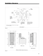
Page 31: ...Installation Diagrams 29 ...
Page 35: ...I T E Mechanical Interlock M15404 33 Figure 7 ...
Page 41: ...Installation Diagrams 39 ...
Page 49: ...Installation Diagrams 47 ...
Page 50: ...48 I T E Panelboard Connecting Straps 1 ...
Page 53: ...Installation Diagrams 51 ...


