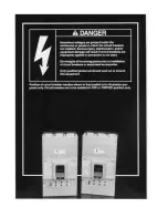
I-T-E MD and ND-Frame Installation Instructions
5
General
NOTE: This instruction page outlines the recommended
installation procedure.
The MD and ND Frame circuit breaker line includes types
SMD6, SHMD6, SCMD6, SND6, SHND6 and SCND6 circuit
breaker types. These devices are rated for operating volt-
ages up to 600 V AC, 50/60Hz.
Installation of Breaker
SMD and SND Circuit Breaker devices are for use in indi-
vidual enclosures, panelboards, switchboards or other ap-
proved equipment.
The installation procedure consists of inspecting, attaching
required accessories, mounting the device and connecting
and torquing the line and load wire connectors.
Mounting hardware and unmounted wire connectors (where
required) are available as separate catalog items.
A.
Turn off and lock out all power before installing or
servicing.
B.
Make sure that the device is suitable for the installation
by comparing nameplate ratings with system require-
ments. Inspect the device for completeness and check
for any damage before mounting.
C.
Device must be in TRIPPED or OFF position prior to
mounting.
D.
To mount the device perform the following steps:
1.
For individual enclosures, panelboards and switch-
boards manufactured by Siemens Energy & Auto-
mation, Inc., follow the instructions provided with
this equipment.
2.
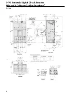
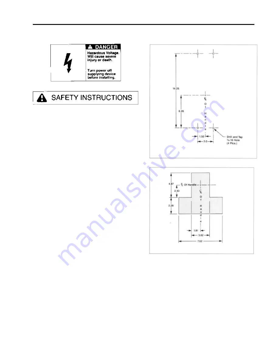
For those applications where mounting is on a flat
surface of the customers equipment, drill and tap
mounting bolt holes according to the drilling plan in
Figure 1. For handle escutcheon cut out plans refer
to Figure 2.
3.
If device contains internal accessories, make sure
terminals can be connected when the circuit breaker
is mounted.
4.
Position device on mounting surface.
5.
Install mounting screws and washers. Tighten hard-
ware securely.
5.
After mounting the device, line and load terminals
and accessory terminals should be connected.
6.
After the device is installed, check all mounting
hardware for secureness. Check wire connectors
for correct torque requirements. Torque values for
line and load connectors are provided on the device
nameplate.
Figure 1
Figure 2
Summary of Contents for I-T-E Sensitrip MD Series
Page 2: ......
Page 6: ...4 I T E Sensitrip Digital Circuit Breaker MD and ND Frame Outline Drawings 1 3 Pole ...
Page 8: ...6 MD and ND Frame Trip Adjustments ...
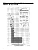
Page 12: ...10 MD and ND Frame Time Current Curve 600 1000A With Short Time Delay Set on Fixed Time ...
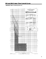
Page 13: ...MD and ND Frame Time Current Curve 11 1200A With Short Time Delay Set on Fixed Time ...
Page 14: ...12 MD and ND Frame Time Current Curve 600 100A With Short Time Delay Set on I2 t ...
Page 15: ...MD and ND Frame Time Current Curve 13 1200A With Short Time Delay Set on I2 t ...
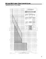
Page 16: ...14 MD and ND Frame Time Current Curve 600 100A Without Short Time Settings ...
Page 17: ...MD and ND Frame Time Current Curve 15 1200A Without Short Time Settings ...
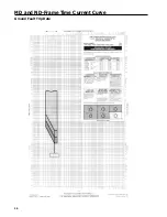
Page 18: ...16 MD and ND Frame Time Current Curve Ground Fault Trip Data ...
Page 19: ...MD and ND Frame Time Current Curve 17 Example ...
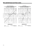
Page 20: ...18 MD and ND Frame Let Thru Curves ...
Page 31: ...Installation Diagrams 29 ...
Page 35: ...I T E Mechanical Interlock M15404 33 Figure 7 ...
Page 41: ...Installation Diagrams 39 ...
Page 49: ...Installation Diagrams 47 ...
Page 50: ...48 I T E Panelboard Connecting Straps 1 ...
Page 53: ...Installation Diagrams 51 ...


