2
The ICP-B6 module can be used in four
different ways:
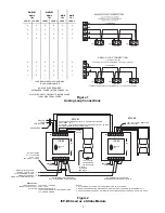
1. Using the ICP-B6 as an NAC Module
This notification appliance application uses the
principle of polarity reversal when there is an
alarm. Figure 2 shows the polarity connection
in a supervisory condition. When using the
ICP-B6 as a supervised NAC output module
with notification appliance devices, cut jumper
JP2. Refer to Figure 2 for additional connec-
tion and jumper information, and to P/N 315-
096363 for a list of compatible devices.
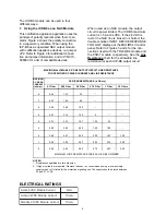
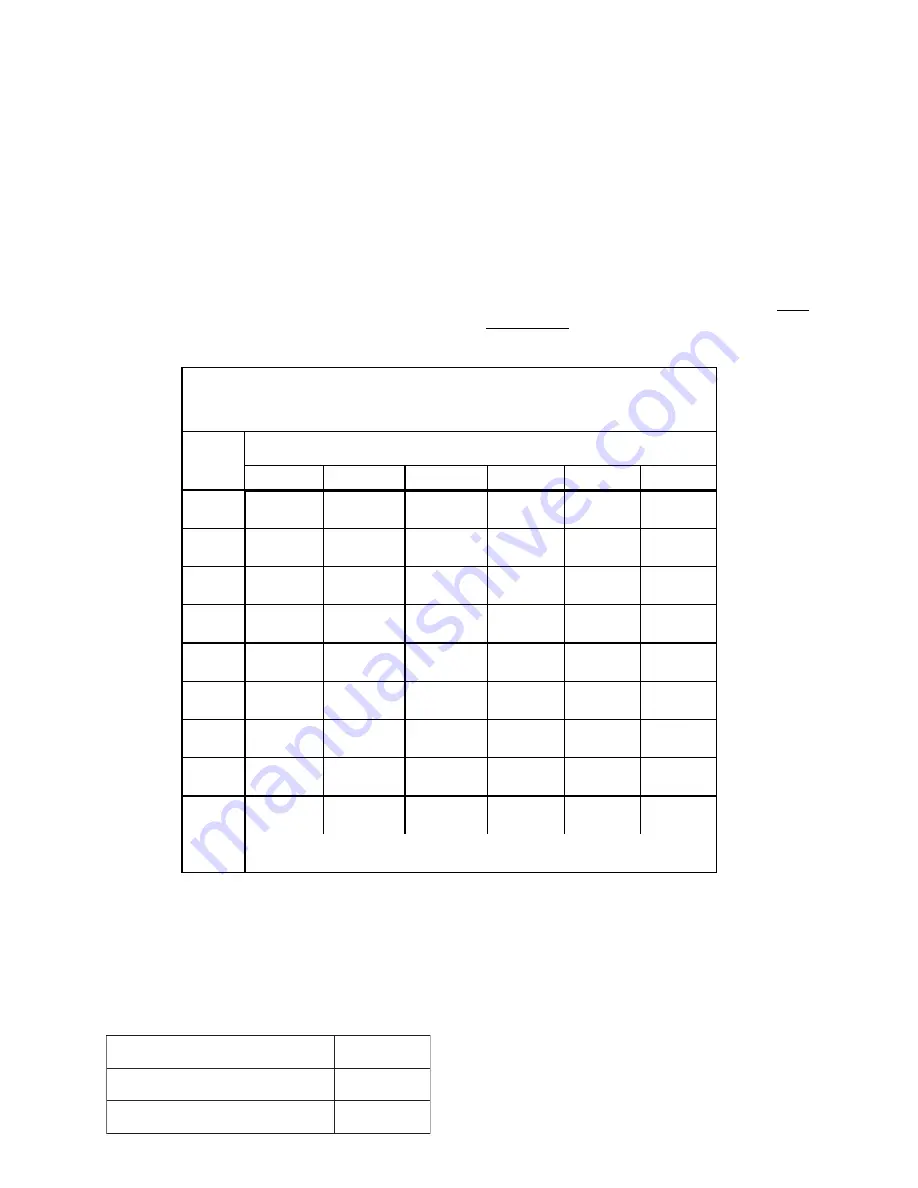
MAXIMUM ALLOWABLE ICP-B6 OUTPUT CIRCUIT LINE RESISTANCE
FOR SPECIFIED DC RISER CURRENT AND LINE RESISTANCE
MAXIMUM
DC RISER
CURRENT
(in Amps)
DC RISER RESISTANCE (in Ohms)
0.1 Ohm
0.25 Ohm
0.5 Ohm
0.75 Ohm
1 Ohm
1.5 Ohms
8
2.46
1.67
.33
--
--
--
7
2.53
1.83
.66
--
--
--
6
2.60
2.00
1.00
--
--
--
5
2.67
2.16
1.33
.5
--
--
4
2.73
2.33
1.67
1.00
.33
--
3
2.80
2.50
2.00
1.50
1.00
--
2
2.86
2.67
2.33
2.00
1.67
1.00
1
2.93
2.83
2.67
2.50
2.33
2.00
.5
2.96
2.92
2.83
2.75
2.67
2.50
MAXIMUM LOOP RESISTANCE FOR EACH ICP-B6 ON RISER
NOTES:
1. Resistances specified are for both wires.
2. If higher currents are required, Siemens Industry, Inc. recommends using a local auxiliary
supply which is UL listed for fire protection signaling use. The supply should be rated between
24 and 27.3 VDC.
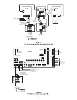
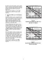
When used as an NAC module, the output
circuit is power limited. The ICP-B6 maximum
current is 1.5A at 24 VDC. If the 24 VDC is
lost or the NAC line is broken or shorted, the
trouble condition INPUT DEVICE RESPONSE
TOO LOW displays at the MXL/MXLV control
panel. Refer to Figures 3 and 4 for the con-
nections used with the TRI-60/B6 module and
the PSR-1 module, respectively. See the Line
Resistance chart for the allowable line
resistance for each ICP-B6 output circuit.
ELECTRICAL RATINGS
t
n
e
r
r
u
C
e
l
u
d
o
M
C
D
V
5
e
v
i
t
c
A
A
m
0
t
n
e
r
r
u
C
e
l
u
d
o
M
C
D
V
4
2
e
v
i
t
c
A
A
m
0
1
t
n
e
r
r
u
C
e
l
u
d
o
M
C
D
V
4
2
y
b
d
n
a
t
S
A
m
0
1


