5
2. Using the ICP-B6 as a Telephone Zone
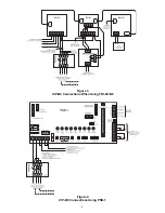
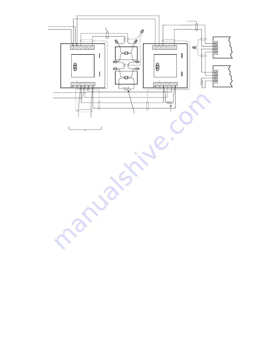
When the ICP-B6 is used as a telephone zone
module, the 24 VDC provides supervision,
trouble, and call-in conditions. If the 24 VDC is
lost, the trouble condition INPUT DEVICE
RESPONSE TOO LOW displays at the MXL/
MXLV and an LED for that zone lights at the
VSM-1 module.
The supervised telephone common talk riser
starts at the TBM module in the MME-3 back-
box. The Class B shielded cable connects
continuously to each ICP-B6 with a 5.6K end of
line device. Tie the shield of these riser wires
and the shield of the zone output wires together
using terminal 5 of TB2 and isolate them from
the system circuits and the earth ground.
Connect the supervised individual zone output
connections from each ICP-B6 to the field
telephone with shielded cable. Terminate
them at the last station with a 10K ohm end of
line resistor. As with the common talk line
described in the paragraph above, be sure
that the shield is continuous and isolated
Figure 5
ICP-B6 Used as a Telephone Zone
+
+
+
+
+
-
-
-
-
-
ANALOG LOOP
CONNECTION
FJ-303
FJ-303
BLACK
BLACK
BLACK
BLACK
WHITE
WHITE
WHITE
WHITE
SHIELD
SHIELD
SHIELD
WARDEN'S STATIONS
MODELS FT-301 SERIES
AND FT-302 SERIES
24 OHMS MAX
10K, 1/2W, +/-5%
EOL RESISTOR
P/N 140-112172
AT LAST STATION
ICP-B6 DC SUPPLY
FROM MMB, PSR-1, OR
UL LISTED POWER SUPPLY
MANUFACTURED BY ALARM-SAF
Model BN4-002-UL (SUPERVISED)
FROM PREVIOUS ICP-B6, OCC-1,
OR TBM
(20 OHMS MAXIMUM
LINE RESISTANCE)
COMMON TALK RISER
18 AWG MINUMUM
BELDON 8760 OR EQUIVALENT
OR AS REQUIRED BY
THE LOCAL AUTHORITY
HAVING JURISDICTION
RISER
NOMINAL VOLTAGE:
MAXIMUM CURRENT:
17.5 VDC
175 mA
10K, 1/2W, +/-5%
EOL RESISTOR
P/N 140-112172
AT LAST FJ-303
5.6K, 1/2W, +/-5%
EOL RESISTOR
ELECTRICAL:
INPUT DC SUPPLY:
SUPERVISORY OUTPUT:
ACTIVATED OUTPUT:
20.5 TO 30 VDC, 18mA MAX
8V, .8mA
11V, 70mA
SUPERVISED
POWER LIMITED
FROM MXL MMB OR
ALD-2I ON MOM-4
(12 MAX ICP-B6
MODULES PER LOOP)
(SUPERVISED)
NOTES:
1. THE SHIELD ON THE COMMON TALK LINE MUST BE CONTINUOUS
AND CONNECTED ONLY TO DC COMMON AT CONTROL PANEL.
2. ALL WIRING MUST CONFORM TO NATIONAL AND LOCAL CODES.
3. POSITIVE AND NEGATIVE GROUND FAULT DETECTED AT <5K OHMS FOR TERMINALS 3-6.
ICP-B6
ICP-B6
PROGRAM
PLUG
PROGRAM
PLUG
TB1
TB1
6
6
5
5
4
4
3
3
2
2
1
1
+
+
+
+
-
-
-
-
JP2
JP2
JP1
JP1
SHIELD
SHIELD
SHIELD
SHIELD
SHIELD
+
+
-
-
TB2
6
5
4
3
2
1
SHIELD
TO
EARTH
+
+
+
-
-
-
TB2
6
5
4
3
2
1
SHIELD
TO
EARTH
from both system circuits and earth
ground and that the shields are connected
together using terminal 5 of TB-2.
3. Using the ICP-B6 as a 70 Volt Speaker
Zone
When the ICP-B6 is used as a speaker zone,
the 24 VDC provides the supervision. If the 24
volts is lost or there is an open or shorted
speaker output line, the trouble condition
INPUT DEVICE RESPONSE TOO LOW
displays at the MXL/MXLV and the related
zone LED on the VSM-1 lights.
The 70.7V RMS audio input comes from the
amplifier via the ASC-2 Amplifier Supervision
card. The ASC-2 supervises the audio con-
nection path to the ICP-B6 and provides up to
100 watts of power. The ASC-2 can be used
as Style Y (Class B) or Style Z (Class A). Refer
to the ASC-2 Instructions, P/N 315-092085.
When the ICP-B6 is used as a speaker zone,
the output speaker lines are supervised and
power limited. The audio output cannot exceed


