6
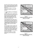
25 watts. Connect the speaker output as either
Style Y (Class B) or Style Z (Class A). Figure 6
gives the approximate decibel loss for the total
speaker zone wire length for various wire
gauge sizes.
When using the ICP-B6 as a 70.7V RMS
speaker zone, cut the JP1 jumper. (See
Figure 8.)
4. Using the ICP-B6 as a 25 Volt Speaker
Zone
When the ICP-B6 is used as a speaker zone,
the 24 VDC provides the supervision. If the 24
volts is lost or there is an open or shorted
speaker output line, the trouble condition
INPUT DEVICE RESPONSE TOO LOW
displays at the MXL/MXLV and the related
zone LED on the VSM-1 lights.
The 25V RMS audio input comes from the
amplifier via the ASC-2 Amplifier Supervision
card. The ASC-2 supervises the audio con-
nection path to the ICP-B6 and provides up to
100 watts of power. The ASC-2 can be used
as Style Y (Class B) or Style Z (Class A).
Refer to the ASC-2 Instructions, P/N 315-
092085.
When the ICP-B6 is used as a speaker zone,
the output speaker lines are supervised and
power limited. The audio output cannot
exceed 35 watts. Connect the speaker output
as either Style Y (Class B) or Style Z (Class
A). Figure 7 gives the approximate decibel
loss for the total speaker zone wire length for
various wire gauge sizes.
When using the ICP-B6 as a 25V RMS
speaker zone, cut the JP2 jumper (See
Figure 9).
Figure 6
Approximate Speaker Zone Wire Loss
with the 70.7V Option
Figure 7
Approximate Speaker Zone Wire Loss
with the 25V Option


