background image

Doc-1552 2019-01-30 


IQHeat 


User manual 

Summary of Contents for IQHeat

Page 1: ...Doc 1552 2019 01 30 IQHeat User manual ...

Page 2: ...hout further notice make changes and improvements to the content in this manual if it is necessary due to printing mistakes wrong information or changes in the hardware or software All these types of changes will be included in future release of the manual ...

Page 3: ... valve modes 15 6 2 Frost protection 15 6 3 System objects 16 6 3 1 Plant information 16 6 3 2 Restoring the start up settings 16 6 3 3 Language selection 16 7 Heating circuit 17 7 1 Operating mode heating 17 7 2 Heat time program 18 7 3 Setting the value for the heating circuit 19 7 4 Setting the heating curve 19 7 5 Heating Limit ECO 20 7 5 1 Setting Heating limit ECO 21 7 5 2 Heat limit functio...

Page 4: ...for IQHeat 38 12 1 Standard services 38 12 2 Optional services 38 13 Troubleshooting 39 14 Options 40 14 1 Expansion module AHU with 14 I O 40 14 1 1 Setting expansion module s DIP switches 41 14 1 2 LEDs for BSP and BUS diagnostics 41 14 2 Communication module Web Adv Web 42 14 2 1 Services associated with Adv Web 42 14 3 Communication module BacNet IP 42 14 4 Communication module ModBus 42 14 5 ...

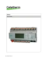
Page 5: ...n The sensors allow for the effective limitation of return temperatures and simple monitoring and remote troubleshooting of functional or comfort problems IQHeat is always factory tested and factory set IQHeat are available in different models IQHeat50 serves one heating circuit IQHeat60 serves two separate heating circuits IQHeat100 serves one heating circuit and one hot water circuit IQHeat110 s...

Page 6: ...set The processing unit has the following characteristics RS 485 ModBus RTU for third party bus full modem port RS 232 for remote service process bus for connecting room units and external control panel DPSU up to three additional communication modules for integration into the master system local service contact for control panel RJ45 and PC tools USB SD card to upgrade applications and software v...

Page 7: ... BUS for diagnostics The LEDs can light with three different colours yellow green and red BSP indicates the status of the internal program in DDC1 BUS indicates the status of the external communication BSP LEDs Start Stop Mode Status LED BSP Software update mode download of application or new software LED BSP lights every second alternating between red and green No application is loaded Yellow LED...

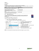
Page 8: ...The processing unit can be upgraded with an SD card FAT16 model max 2GB When upgrading connect the SD card to the memory card reader at the top right side of the processing unit The upgrade requires logging in at service level There are two options for loading from SD card Apply only control parameters loaded recommended Full all settings given new values including IP addresses and the like 1 From...

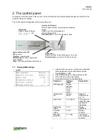
Page 9: ...Select Imperial unit sys Passive Active Passive imperial units e g C Reset time 0 30 min Login again is necessary after this time of inactivates Brightness inbuilt 0 31 Display brightness Contrast inbuilt 0 99 Display contrast Message durat inb 0 15 s The time an error message is shown Info button Push to change between Main overview and Main index Select and OK knob Turn to select menues paramete...

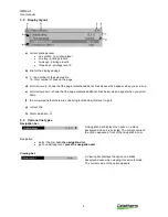
Page 10: ...e page contains additional lines below which appear when you scroll down f the arrow means that there are underlying levels below this level to go to g current line h Alarm indication 3 3 Various line types Navigation bar A navigation bar displays the option on a black background when it is selected The current value of the option appears in front of the navigation arrow Navigation select the line...

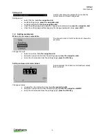
Page 11: ... 4 Setting parameters When only one value is selectable The line with a tick in front Fire Set point shows the set value Change the value select new value turn the navigation dial apply the new value and close the settings page press the navigation dial keep the old value and close the settings page press the ESC key Setting analogue parameter values A scale displays the minimum and maximum values...

Page 12: ...history can be acknowledged and reset Service level level 4 password 2000 Used for configuring I Os and system settings Only qualified service personnel should make changes at this level appears with two keys in the upper left corner of the display all rights as for End users access to all menus except I O configuration and system settings OEM level 2 appears with three keys in the upper left corn...

Page 13: ...s Info to access Main overview 2 The top line shows the set date and time 4 2 2 Setting date and time Requires login at end user level 1 Press Info until the page with the date and time are displayed 2 Move the cursor to the line for date and time 3 Press OK to edit the day 4 Set the correct day with the navigation dial press OK to confirm and continue to edit the month and year 5 Continue to edit...

Page 14: ...nd date when the alarm was sent This also includes information on when the alarm was actioned Incoming alarms are indicated by a plus before the name while actioned are indicated by a minus When the Alarm list is empty there should be as many as entries in the Alarm history 5 1 Alarm list The Alarm list contains all active alarms acknowledged and unacknowledged The Alarm list may contain up to 50 ...

Page 15: ...ned are now listed Number of alarms in the list Alarm name Status 3 To see detailed information about an alarm select the desired alarm by using the navigation dial and press OK 5 3 Settings NOTE Requires login at end user level In the Alarming under Advanced you can see how many alarms there are in the Alarm list and Alarm history Here you can also set the sort order for how alarms are presented ...

Page 16: ... alarm sensor A Hot water supply Function alarm sensor A Primary Supply Function alarm sensor B Outside temperature Function alarm sensor A Outside temperature is set to 1 C Heating circuit Return Function alarm sensor B High level high and low pressure Heating circuit pressure level Level alarm pressure B High level or high and low pressure Temp deviation Heat Control deviation heating circuit B ...

Page 17: ... This function is installed to protect buildings and heating systems from frost The hot water circuit also has a frost protection function that cannot be turned off For each heating circuit and hot water circuit it is possible to set a range of temperatures to enable the frost protection If the pumps are turned off in manual pump mode this function does not apply The frost protection for the plant...

Page 18: ...on 3 To check the current versions on connected parts select Versions 6 3 2 Restoring the start up settings For more information on start up settings see 9 5 Save and reset start up settings and factory settings 1 From the Main index select Systemobjects 2 Select Save load and press OK 3 Select Execute and press OK to return to the start up settings 6 3 3 Language selection Here you can set the pr...

Page 19: ...one heating circuit 1 HC1 appears in these instructions NOTE Access to the menys in this chapter requirer login at end user level 7 1 Operating mode heating The heating circuit can be set in one of four operating modes Auto the plant is controlled by the time program see 7 2 Heat time program BuildProt the plant is shut down but is automatically started when the outside temperature is lower than t...

Page 20: ... 00 00 This cannot be changed 5 Use the navigation dial to select the desired values and transit times for Value 1 Value 6 and Time 2 Time 6 Confirm each selection by pressing OK 6 Press ESC to exit the menu In the example the current heating circuit on Mondays is in Economy mode from midnight 00 00 to 7 00 when it switches to Comfort mode At 09 00 it reverts back to Economy mode and remains in th...

Page 21: ...Flow temp design P1 25 130 C Heating Curve Setp fl temp high P5 0 65 C 7 4 Setting the heating curve The heat curve is a 7 point heating curve where point 1 is a maximum limit and point 7 is a minimum limit The five points 2 6 is what forms the heating curve Points 2 6 can be adjusted at end user level while adjusting points 1 and 7 requires logging in at service level The design outside temperatu...

Page 22: ... 7 5 Heating Limit ECO The control has a built in ECO function The ECO function ensures that heat is only started when needed This means that savings are made for pump energy and ensures that no heat is present on the radiator side when it is not needed The temperature limit for when the heat is turned off is the result of the operating mode s set point minus the Heating limit ECO Example The cont...

Page 23: ...hours and the current outside temperature For quick changes it is appropriate to respond in part directly without waiting for the full change of the estimated outside temperature NOTE Activating the heat limit function requires login at Service level 1 Press Info to access the Main index 2 Now select Commissioning Plant Config Heating circuit s 3 Select the ECO function and press OK 4 Select prefe...

Page 24: ...offset NOTE Parallel offsetting of the heating curve requires login at Service level 1 Press Info to access the Main index 2 Now select Commissioning Plant settings Heating circuit 3 Select Flow temp shift and press OK 4 Select the number of degrees for parallel offset of the heating curve 10 C 0 C and press OK ...

Page 25: ...lect Operating mode and press OK 3 Select preferred operating mode and press OK Auto PlantProt Reduced Normal recommended 8 2 Setting the set point for the hot water circuit All countries have different rules for how hot or cold tap water should be Cetetherm recommends the hot water temperature is at least 55 C and a hot water circulation not less than 50 C At a temperature below 50 C there is a r...

Page 26: ... how the heating will be affected to provide the best comfort and economy The building time constant is used to calculate the parameter calculated outside temperature Typical values for setting the building time constant Thick walls Stone building 30 60 hours Modern light building with good insulation 20 50 hours Light building thin insulation 10 20 hours 1 From the Main index select Commissioning...

Page 27: ...the Main index select Commissioning 2 Now select Plant settings Common 3 Select the parameter to be changed and press OK 4 After each parameter change press OK to save the new settings Parameter Settings range Explanation Plant frost Yes No Enable frost protection for the plant Setp plant frost 4 15 At which the temperature function frost protection is enabled ...

Page 28: ... at 00 00 Sa 07 00 every Saturday at 07 00 exercising activated in ranges Duration 0 200 s Sets the time for exercising E g 10 duration of 10 seconds Standby time 0 2000 t Time between activation times E g 168 after 168 hours NOTE Pump valve kick and Standby time 0 means no pump exercising 9 5 Save and reset start up settings and factory settings The first time IQHeat is started the Service settin...

Page 29: ...ct Commissioning 2 Now select Plant Settings Domest hot water 3 From the HW settings menu select the parameter to be changed and press OK 4 After each parameter change press OK to save the new settings Parameter Settings range Explanation Setpoint legion 55 100 C The hot water is raised to this temperature to prevent bacterial growth Time legion 00 00 23 59 Time when the function is enabled Legion...

Page 30: ... 36000 s After the set time the function is enabled after start Delay 0 65535 s Time delay for high and low priority alarms Priority Plant off A Plant stopped Critical A Plant shut down Low B Affected part of the plant is shut down Warning C Only message No alarm No message no alarm 4 Select Flow temperature 5 Select the value to be changed press OK Parameter Settings range Explanation High limit ...

Page 31: ... Parameter Settings range Explanation Legion function No Yes Circ Pump Not active Active Legionella function with circulation pump is recommended Alarm flow temp Yes No Activation of the deviation alarm Time schedule No Yes Time sch cir pump No Yes No schedule Common schedule 9 9 System objects settings 9 9 1 SMS alarm 1 From the Main index select Systemobjects 2 Now select Communication SMS Setti...

Page 32: ... connect the accompanying TP cable to the output for Internet traffic The communication module is set in DHCP mode i e it gets its address automatically from the server If a fixed IP address is used this can be set via the Operator panel Here is a description of how to set the IP address The IP Mask and Gateway are set in the same way 1 From the Main index select Systemobjects 2 Now select Communi...

Page 33: ...cription of how to set the IP address The IP Mask and Gateway are set in the same way 1 From the Main index select Systemobjects 2 Now select Communications IP configuration 3 Select Given IP and enter the desired IP address 4 Press OK to save the new settings 5 Restart to activate the settings ...

Page 34: ... to update the measurement values 1 From the Main index select Systemobjects 2 Now select Communication Communic modules 2 M Bus module 3 Press OK to save the new settings 4 Restart to activate the settings 9 12 Read and change the ModBus parameters 9 12 1 RS485 To check and if necessary change so that the master unit uses the same address and parameter ModBus RTU RS485 1 From the Main index selec...

Page 35: ...in the master system 1 From the Main index select Systemobjects 2 Now select Communication ModBus IP Config 3 Select the parameter to be changed press OK 4 After each parameter change press OK to save the new settings 5 Select Restart press OK 6 Select Execute and press OK The new settings take effect after restart ...

Page 36: ...active until it is set to Passive For the control to work the cable test in normal operation must be set to Passive 1 From the Main index select Commissioning 2 Select Wiring test 3 Set Wiring test in Active mode press OK 4 Read the test results by selecting Heating Circuit 1 or Domest hot water 5 The cables were OK and this is indicated by the three OKs in the image opposite 6 Wiring test is to b...

Page 37: ...st be set in the same position as before the test 6 Wiring test is to be set to Passive after the test 10 3 Testing the valves All the valves are tested in the same manner Here is a description of the test of the primary circuit valve Wiring test must be active when testing the valves The test shows if the valves and their control are correctly connected NOTE Wiring test is active until it is set ...

Page 38: ...r The plant is turned off when a Calendar stop is enabled NOTE To change in the exception calendar login at End user level is required 1 From the Main index select Common 2 Now select Calendar 3 Select the parameter to be changed and press OK 4 After each parameter change press OK to save the new settings Para meter Factory settings Settings range Relates to Choice 1 Choise 10 Invalid Date Range W...

Page 39: ...d Start Date 23 06 09 End date 12 07 09 June 23 2009 through July 12 2009 are exception days e g holidays Start Date 23 12 00 End date 31 12 00 December 23 to 31 is the exception period each year Time End date 01 01 00 does not work as January 1 occurs prior to December 23 Start Date 23 12 09 End date 01 01 10 December 23 2009 through January 1 2010 are exception days Start Date 00 End date 00 War...

Page 40: ...ictor Works best with M Bus IQPump100 Automatic control of secondary pump for heating circuits with 0 10V to optimise cooling on the secondary side Only P1 Kr1 on IQHeat110 are predefined but they also work on P2 Kr2 if an output is available 12 2 Optional services The following services require some form of hardware or special software to work which are not included in the basic version IQWeb200 ...

Page 41: ...t in the heating system The circulation pump is not working Check that the power is on and the fuses are intact If the pump is controlled from the controller station make sure it is running in a day weekly schedule ECO function Check that the pump is not set in manual off mode Too little water in the system Top up the water Air accumulations at the heat exchanger or in heating circuit Bleed the ex...

Page 42: ... and cooling substations All the options are connected to the processing unit with a module to module connector The processing unit and the communication modules programs and data lists can be updated by an SD card There is an SD reader in the processing unit and in the advanced WEB module Even the processing unit s operating systems can be updated in this way whenever necessary See 2 1 2 Upgrade ...

Page 43: ...xpansion module standard IQHeat 50 100 110 With two expansion modules first and then second IQHeat120 14 1 2 LEDs for BSP and BUS diagnostics The expansion module has two LEDs BSP and BUS for diagnostics The LEDs can light with three different colours yellow green and red Status of the LEDs Mode Status LED BUS Communication error Red LED lights Communication OK Green LED lights Communication OK bu...

Page 44: ...or SCOPE 14 4 Communication module ModBus The ModBus communication module connects the processing unit to a ModBus network for reading sensors The ModBus module can be upgraded using an SD card The ModBus module has the following characteristics integration to a building automation system via RS 485 ModBus RTU two ModBus slave communication ports galvanic ally isolated connection to the ModBus net...

Page 45: ... module Mode Status LED BUS IP running and communication ok Green LED lights IP not running Yellow LED lights Hardware or software error Red LED lights 14 6 2 BUS for BacNet Mode Status LED BUS BacNet IP running and communication ok Green LED lights IP not running Yellow LED lights Hardware or software error Red LED lights 14 6 3 BUS for ModBus Mode Status LED BUS All communication running or if w...

Page 46: ...IQHeat User manual 44 15 Overview of available menus The following menus are available when logging in at End User Level ...

Page 47: ...IQHeat User manual 45 ...

Page 48: ...Cetetherm AB Fridhemsvägen 15 372 38 Ronneby Sweden www cetetherm com ...

Reviews: