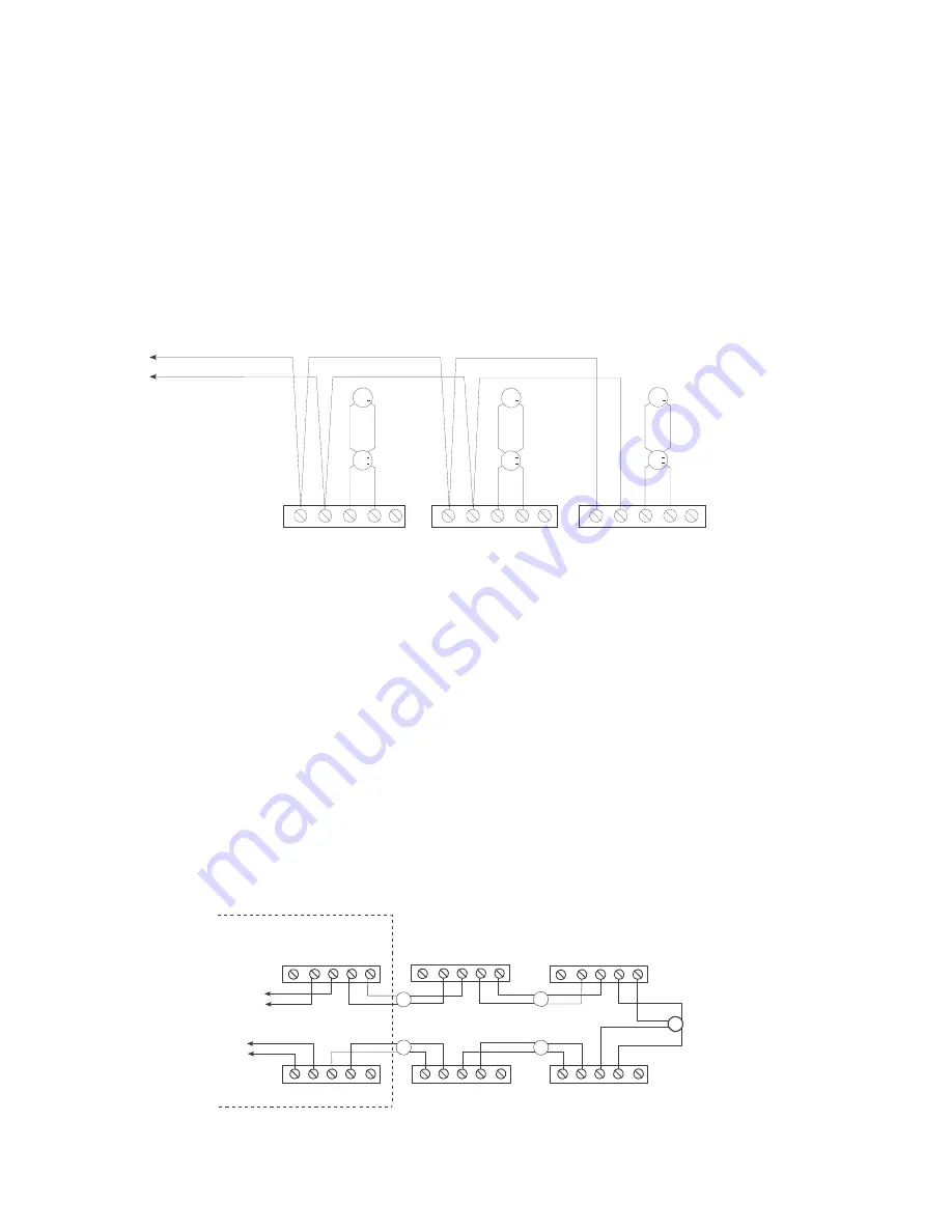
NOTES for Figure 3:
1. All wiring must comply with national and local codes.
2. In order to provide adequate protection, it is recommended
that you do not install more than 20 devices on a single LIM-1.
3. Minimum wire gauge is 18 AWG.
4. The total wire resistance (both wires) between LIM-1s
cannot exceed 10 ohms.
5. Do not install more than 12 LIM-1s per loop.
6. All circuits are supervised.
7. Refer to the MXL/MXLV Manual, P/N 315-092036, the MLC
Installation Instructions, Document ID A6V10328217, or the
DLC Installation Instructions, Document ID A6V10239107,
for the list of compatible devices.
8. All terminals are power limited.
ANALOG LOOP
IN
+
-
IN
+
OUT
+
+
+
-
OUT EARTH
IN
+
-
IN
+
OUT
+
+
+
OUT
-
EARTH
IN
+
-
IN
OUT
+
+
+
+
OUT
-
EARTH
NOTE: WHEN USING THE
LIM-1 WITH THE DLC,
THE FOLLOWING
POLARITY MUST BE
OBSERVED AT THE LIM-1.
DLC LINE 1 = +
DLC LINE 2 = -
Figure 3
LIM-1 Wiring Diagram
Class B Installation
The LIM-1 may be used in two circuit configurations.
Class B (See Figure 3)
In Class B wiring each LIM-1 isolates a branch on the
circuit. Note that a short on the main branch causes
the entire loop to fail. To prevent this, mount the
LIM-1s at the MXL or FireFinder-XLS enclosure and
run each branch independently.
TO ANALOG
LOOP RETURN
INSIDE ENCLOSURE
TO ANALOG
LOOP FEED
IN
IN OUT OUT
IN
+
+
+
+
+
+
+
+
+
+
+
+
- -
+
+
-
-
-
-
-
-
-
-
-
-
-
-
IN
OUT
OUT
EARTH
EARTH
IN
IN
OUT
OUT
EARTH
IN
IN
OUT
OUT
EARTH
IN
IN OUT OUT EARTH
IN
IN OUT OUT EARTH
+
- -
+
+
-
-
+
+ -
-
+
+
-
-
+
NOTE: WHEN USING THE LIM-1 WITH THE
DLC, THE FOLLOWING POLARITY MUST BE
OBSERVED AT
THE LIM-1.
DLC LINE 1 = +
DLC LINE 2 = -
Figure 4
LIM-1 Wiring Diagram
Class A Installation (Single Loop)
Class A Single Loop (See Figure 4)
In Class A wiring the LIM-1s are wired in series with
the loop wiring. This results in a single continuous
loop. If any group in the loop has a short, that group is
lost and a Class A circuit failure results. The MXL or
FireFinder-XLS displays communication errors for the
devices and a Class A failure for the loop itself.
NOTES for Figure 4:
1. All wiring must comply with national and local codes.
2. In order to provide adequate protection, it is recommended
that you do not install more than 20 devices on a single LIM-1.
3. Minimum wire gauge is 18 AWG.
4. The total wire resistance (both wires) between LIM-1s
cannot exceed 10 ohms.
5. Do not install more than 12 LIM-1s per loop.
6. All circuits are supervised.
7. Refer to the MXL/MXLV Manual, P/N 315-092036, the MLC
Installation Instructions, Document ID A6V10328217, or the
DLC Installation Instructions, Document ID A6V10239107,
for the list of compatible devices.
8. All terminals are power limited.
P/N 315-049552-6
Document ID A6V10239166


