39/116
Smart Infrastructure
Basic Documentation LME7...
CC1P7105enr
4
Technical
data
24.07.2020
4.12.3 QRB1/QRB3/ QRB4
No-load voltage at the QRB4 terminal
(X10–05, terminal 3)
Approx. 5 V DC
Required detector current in operation
Min. 20 µA (display intensity approx.
35%)
Possible detector current in operation
Max. 60 µA (display intensity 100%)
Perm. length of detector cable
(normal cable, laid separately) ¹)
Max. 3 m (core-core 100 pF/m)
¹)
Multicore cable not permitted
Notes
Increasing line capacitance between QRB connection and “L” mains phase impairs
sensitivity. Always run detector cables separately
Before using a highly sensitive QRB1B and QRB3S, check carefully whether they
are necessary
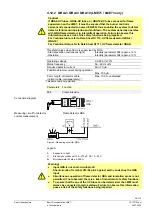
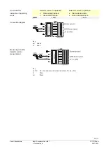
QRB4 cable connection!
Blue QRB4 cable to terminal X10-05 pin 4.
Black QRB4 cable to terminal X10-05 pin 3.
Otherwise the QRB4 will not function.
Check the flame intensity via the AZL2 or the internal LED display (flame current, FL2).
The maximum possible QRB flame current is limited to approx. 60 µA for system-
specific reasons. The maximum display intensity (parameter 954 in the AZL2 or via
internal LED display FL2) corresponds to 100%.
Threshold values when flame is supervised by QRB
Start prevention (extraneous light)
Intensity
AZL2 (parameter 954) or FL2 >10%
Flame current
>10 µA
Operation, minimum required flame signal
Intensity
AZL2 (parameter 954) or FL2 >35%
Flame current
Approx. 20 µA
Signaling good/bad flame (LED starts flashing green during operation)
Intensity
AZL2 (parameter 954) or FL2 approx. 50%
Flame current
Approx. 30 µA
Typical flame signal during operation
Intensity
AZL2 (parameter 954) or FL2
≥
60%
Maximum flame signal during operation
Intensity
AZL2 (parameter 954) or FL2
≤
100%
Flame current
Approx. 60 µA
Parameters Function
954
Flame intensity
The values specified in the table only apply under the following ambient conditions and
may vary under other conditions:
Mains voltage 230 V AC
Ambient
temperature
23°C

