background image


87/116 

Smart Infrastructure  

Basic Documentation LME7... 

CC1P7105en 


13 Operation via AZL2 

24.07.2020 


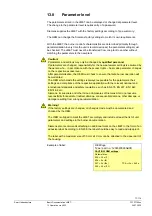
13.9 

Operating variants of the parameters 

 
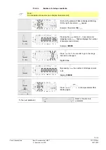
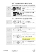
The parameters stored in the LME7 can be displayed and changed at parameter level. 
 

VSD

A

F


>1 s 


Press button combination 

VSD

A

F

 to display 

000: Int

.  

With 

, select the parameter group 

100: 

PArA


With 

, select the parameter group 

200: 

PArA

Pressing the 

/reset

 button takes you to 

parameter 

226:

 Preignition time. 


13.9.1 

Parameters without index, with direct display 

13.9.1.1. 

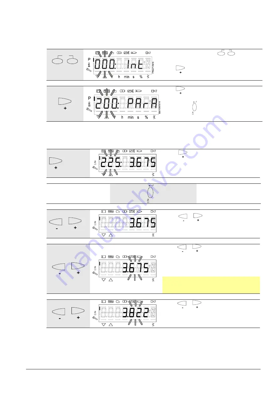
Example of parameter 225 (prepurge time) on the parameter level 


P

V

h min s

%

B

ild

 166

/1

1

0

7


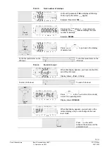
Press 

 for 

prepurge time

 
Display: Parameter 

225:

 blinks, value 

3.675


does not. 


/reset


 or 


P

V

h min s

%

B

ild

 167

/1

1

0

7


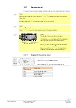
Press 

 or 

 for editing mode. 

 
Display: 

3.675


 or 


P

V

h min s

%

B

ild

 168

/1

107


Press 

 or 

 to shift the former prepurge 

time to change mode one place to the left. 
 
Display: Prepurge time 

3.675

 blinks. 


Note: 
To detect display errors, the value appears 
one place shifted to the left. 


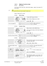
 or 


P

V

h min s

%

B

ild

 169

/1

107


Press 

 or 

 for the required prepurge 

time. 
 
Display: Prepurge time 

3.822

 blinks. 


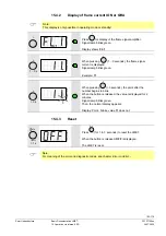
Summary of Contents for LME71

Page 1: ... 03 CC1P7105en 24 07 2020 Smart Infrastructure LME71 LME72 LME73 Burner control Basic Documentation The LME7 and this Basic Documentation are intended for use by OEMs which integrate the burner controls in their products ...

Page 2: ... Program module User Documentation A7105 23 PME73 820Ax Program module User Documentation A7105 24 PME73 830Ax Program module User Documentation A7105 25 PME73 831Ax Program module User Documentation A7105 26 PME73 840Ax Program module User Documentation variant 1 A7105 27 PME73 840Ax Program module User Documentation variant 2 A7105 28 LME73 231Ax Program module User Documentation A7105 29 LME Bu...

Page 3: ...keup function description 16 2 1 Features 17 3 Type summary 18 3 1 Burner controls 18 3 2 Program module 19 3 2 1 PME7 with mains voltage AC 120 V 19 3 2 2 PME7 with mains voltage AC 230 V 21 3 3 External display and operating units 23 3 4 Flame detectors 24 3 5 Actuators 25 3 6 Pressure switch 25 3 7 Dummy plugs for RJ11 25 3 8 Connector sets for LME7 26 3 9 Service tools 27 4 Technical data 28 4...

Page 4: ...e 45 6 6 2 Repetition in case of no flame is established by the end of safety time TSA 45 7 Operation indication diagnostics 46 7 1 Operation 46 7 2 Indication of operating state 46 7 3 Diagnostics of cause of fault 47 8 Inputs outputs 49 9 Connection diagram AGG9 connector 50 9 1 LME71 50 9 2 LME72 51 9 3 LME73 52 10 LME7 burner control 53 10 1 Description of inputs and outputs 53 10 2 Digital in...

Page 5: ... Standardization of modulation range 59 11 7 Setting the minimum power control step dead band parameter 123 in modulating mode via analog input signal terminal X65 LME71 LME73 only 60 User limitations application examples 61 12 Safety notes relating to operation of AZL2 62 13 Operation via AZL2 63 13 1 Description of the unit display and buttons 63 13 2 Meaning of symbols on the display 64 13 3 Sp...

Page 6: ...rect display 87 13 9 1 1 Example of parameter 225 prepurge time on the parameter level 87 13 9 2 Parameters without index with no direct display 89 13 9 2 1 Example of parameter 224 specified time air pressure switch on the parameter level 89 13 9 3 Parameters with index with or without direct display 91 13 9 3 1 Example of parameter 701 Actual error on the service level 91 14 Error code list with...

Page 7: ...the PME7 104 15 5 1 Position of actuator or speed of PWM fan in modulating operation with analog signal 104 15 6 Initial startup with a new PME7 or in case of replacement of the PME7 107 15 7 Manual backup 109 15 7 1 Error during backup process 110 15 8 Manual restore 111 15 8 1 Errors during the restore process 112 15 8 2 Reset 112 16 List of figures 116 ...

Page 8: ...ing space and therefore protected against brush contact when the PME7 is not plugged in Each time work has been carried out mounting installation service work etc check to ensure that wiring and parameterization is in an orderly state and make the safety checks as described in Commissioning notes If not observed there is a risk of impairment of safety functions and of electric shock hazard If the ...

Page 9: ...nt national safety regulations are complied with In the geographical areas where DIN regulations are in use the requirements of VDE must be satisfied especially DIN VDE 0100 0550 and DIN VDE 0722 The LME7 must be secured with fixing screws M4 UNC32 or M5 UNC24 observing a maximum tightening torque of 1 8 Nm at all 3 fixing points The additional bearing surfaces on the housing are provided to impro...

Page 10: ...t spliced wires cannot get into contact with neighboring terminals Use adequate ferrules If this is not observed there is a risk of loss of safety functions or a risk of electric shock For protection the burner manufacturer must fit dummy plugs to unused LME7 terminals The connectors of the connecting cables for the LME7 may only be removed or exchanged when the plant is shut down all polar discon...

Page 11: ...mains powered ionization probe is not protected against electric shock hazard Protection against accidental contact must be ensured Locate the ignition electrode and the ionization probe such that the ignition spark cannot arc over to the ionization probe risk of electrical overloads and that it cannot adversely affect the supervision of ionization Insulation resistance Must be a minimum of 50 M b...

Page 12: ...ith flame detector disconnected Non alterable lockout at the end of the first safety time b Burner startup with flame detector exposed to extraneous light e g to incandescent light with detectors for visible radiation quartz halogen bulb or cigarette lighter flame with detectors for UV radiation Non alterable lockout during the prepurge time c Simulation of loss of flame during operation For that ...

Page 13: ...urning appliances DIN EN 13611 Automatic electrical controls for household and similar use Part 2 5 Special requirements on automatic electric burner control and monitoring systems DIN EN 60730 2 5 Safety and control devices for gas burners and gas burning appliances Valve proving systems for automatic shut off valves DIN EN 1643 The relevant valid edition of the standards can be found in the decl...

Page 14: ...lished by the European Control Manufacturers Association Afecor www afecor org The designed lifetime is based on use of the LME7 according to the manufacturer s data sheet and the basic documentation After reaching the designed lifetime in terms of the number of burner startup cycles or after the corresponding usage time the LME7 must be replaced by authorized personnel The designed lifetime is no...

Page 15: ...e not taken Note draws your attention to important information on the product on product handling or to a special part of the documentation 1 9 2 Qualified personnel Only qualified personnel are allowed to install and operate the equipment Qualified personnel in the context of the safety related notes contained in this document are persons who are authorized to commission ground and tag devices sy...

Page 16: ...tic forced draft burners for gaseous fuels Applications in accordance with EN 746 2 Industrial thermoprocessing equipment Part 2 Safety requirements for combustion and fuel handling systems Type tested and approved in accordance with DIN EN 298 The following items are integrated into the LME7 Burner control BCI for connection a display or PC Only LME72 LME73 Control for one actuator Lockout reset ...

Page 17: ...of fault via blink code Extensive service fault and operating state information via built in 3 x 7 segment display Extensive service fault and operating state information via BCI and AZL2 2 1 Features Undervoltage detection Electrical remote reset facility Accurate control times thanks to digital signal handling Multicolor indication of fault status and operating state messages Air pressure superv...

Page 18: ...A2 S55333 B205 A100 BPZ LME72 000A2 BPZ LME73 000A1 BPZ LME73 000A2 Type LME71 000A1 LME71 000A2 LME71 901A2 LME72 000A2 LME73 000A1 LME73 000A2 Mains voltage AC 120 V Mains voltage AC 230 V Gas pressure switch min POC Pressure switch valve proving Air pressure switch Ionization probe QRA2 QRA4 QRA10 QRB1 QRB3 QRB4 QRC Load controller analog input signal 0 10 V 4 20 mA 0 135 Load controller input ...

Page 19: ...71 000A1 For use with LME72 000A1 For use with LME73 000A1 Gas program forced draft burner Gas program atmospheric burner 1 stage or 1 stage modulating 2 stage or 1 stage modulating Pilot burner simultaneously alternately Modulating via actuator pneumatic or mechanical fuel air ratio control Modulating via PWM fan pneumatic fuel air ratio control Fan speed control control via analog signal 3 posit...

Page 20: ...e with LME73 000A1 Forced draft burner oil program Gas program forced draft burner Gas program atmospheric burner 1 stage or 1 stage modulating 2 stage or 1 stage modulating Pilot burner simultaneously alternately Modulating via actuator pneumatic or mechanical fuel air ratio control Modulating via PWM fan pneumatic fuel air ratio control Fan speed control control via analog signal 3 position step...

Page 21: ...A2 For use with LME73 000A2 Gas program forced draft burner Gas program atmospheric burner 1 stage or 1 stage modulating 2 stage or 1 stage modulating Pilot burner simultaneously alternately Modulating via actuator pneumatic or mechanical fuel air ratio control Modulating via PWM fan pneumatic fuel air ratio control Fan speed control control via analog signal 3 position step signal Actuator contro...

Page 22: ...e with LME73 000A2 Forced draft burner oil program Gas program forced draft burner Gas program atmospheric burner 1 stage or 1 stage modulating 2 stage or 1 stage modulating Pilot burner simultaneously alternately Modulating via actuator pneumatic or mechanical fuel air ratio control Modulating via PWM fan pneumatic fuel air ratio control Fan speed control control via analog signal 3 position step...

Page 23: ...or LME7 degree of protection IP40 See Data Sheet N7542 AZL23 00x9 Article no BPZ AZL21 00x9 Display and operating unit detached choice of mounting methods 8 digit LCD 5 buttons BCI for LME7 degree of protection IP54 See Data Sheet N7542 Built in in the LME7 3 colored LED reset button 3 other buttons for operation in connection with 3 x 7 segment display AGV50 100 Article no BPZ AZL21 00x9 Signal c...

Page 24: ...h Siemens burner controls for the supervision of oil flames in the visible light spectrum The QRB1 is primarily used in connection with burner controls for burners of small capacity Refer to data sheet N7714 QRB3 Photo resistive detector for use with Siemens burner controls for the supervision of oil flames in the visible light spectrum The QRB3 is primarily used in connection with burner controls...

Page 25: ...ta Sheet N7804 SQM40 SQM41 Electromotoric actuators for air dampers and control valves of oil and gas burners of small to medium capacity with UL registered Holding torque running time 5 Nm 15 s until 10 Nm 30 s See Data Sheet N7817 SQM5 Electromotoric actuators for air dampers and control valves of oil and gas burners of small to medium capacity with UL registered Holding torque running time 10 N...

Page 26: ...f 200 pieces each Example X5 03 Article no Type Type of connector Terminal BPZ AGG9 201 AGG9 201 RAST5 X2 09B BPZ AGG9 203 AGG9 203 RAST5 X3 02 BPZ AGG9 209 AGG9 209 RAST5 X10 06 BPZ AGG9 301 AGG9 301 RAST5 X2 01 BPZ AGG9 302 AGG9 302 RAST5 X2 03 BPZ AGG9 304 AGG9 304 RAST5 X4 02 BPZ AGG9 306 AGG9 306 RAST5 X5 01 BPZ AGG9 309 AGG9 309 RAST5 X6 03 BPZ AGG9 310 AGG9 310 RAST5 X7 01 BPZ AGG9 311 AGG9...

Page 27: ... no BPZ OCI410 Interface between burner control and PC Facilitates viewing handling and recording setting parameters on site in connection with the ACS410 software See Data Sheet N7616 ACS410 Article no BPZ ACS410 PC software for setting the parameters and for visualizing the burner controls See Software Documentation J7352 ...

Page 28: ... Safety class I with parts according to II and III in accordance with DIN EN 60730 1 Degree of protection IP00 Note The burner or boiler manufacturer must ensure degree of protection IP40 in accordance with DIN EN 60529 for burner controls through adequate installation of the LME7 Rated surge voltage category III DIN EN 60664 LME7 4 kV Creepage distances or air gaps 2 5 kV due to voltage limitatio...

Page 29: ...terminal X3 02 pin 1 and actuator terminal X2 09 pin 4 status inputs for the contact feedback network are used for system supervision and require mains related input voltage Terminal X3 04 pin 1 and pin 2 Safety loop input See Terminal rating outputs Input currents and input voltages UeMax UN 10 UN 10 UeMin UN 15 UN 15 IeMax 1 5 mA peak peak value 1 mA peak peak value IeMin 0 8 mA peak peak value ...

Page 30: ... or PWM fan motor depending on the fuel train refer to User Documentation A7105 x Rated voltage 120 V AC 50 60 Hz 230 V AC 50 60 Hz Total current 2 A 2 A Power factor Cos 0 4 Cos 0 4 Caution Maximum permissible current load may be exceeded If terminal X2 02 pin 3 is used as the connection for supplying the PWM fan motor no other motor may be connected on terminal X2 01 pin 3 Terminal X2 03 pin 3 A...

Page 31: ...ding on the fuel train refer to User Documentation A7105 x Rated voltage 120 V AC 50 60 Hz 230 V AC 50 60 Hz Rated current Valve proving inactive 2 A 2 A Valve proving active 1 A 1 A Power factor Cos 0 4 Cos 0 4 Terminal X7 04 pin 4 Fuel valve or pilot valve depending on the fuel train refer to User Documentation A7105 x Rated voltage 120 V AC 50 60 Hz 230 V AC 50 60 Hz Rated current Valve proving...

Page 32: ...n 1 to 4 Load controller Max 30 m 100 pF m unshielded Terminal X6 03 pin 1 to 3 Safety valve Max 30 m 100 pF m unshielded Terminal X7 01 pin 1 to 3 X7 02 pin 1 to 3 X7 04 pin 1 to 4 Fuel valve Max 30 m 100 pF m unshielded Terminal X7 01 pin 1 to 3 X7 04 pin 1 to 4 Pilot valve Max 30 m 100 pF m unshielded Terminal X9 04 Multifunctional input valve proving pressure switch refer to User Documentation...

Page 33: ... actuator switching contact used e g cam V2 4 6 Cross sectional areas The cross sectional areas of the mains power lines L N and PE and if required the safety loop safety temperature limiter water shortage etc must be sized for rated currents according to the selected external primary fuse The cross sectional areas of the other cables must be sized in accordance with the primary fuse for the LME7 ...

Page 34: ...2 5 mm Stripping length Approx 8 mm 4 8 RAST3 5 connector Connection cross sections conductor screw connection Stranded conductor fine wired flexible Cross section Min 0 14 mm Max 1 5 mm Stranded conductor fine wired flexible with ferrule Cross section Min 0 25 mm Max 1 mm Stripping length Approx 7 mm Tightening torque screw 0 25 Nm 4 9 Signal cable AGV50 4 9 1 AZL2 BCI Signal cable Color white Un...

Page 35: ...721 3 2 1997 Climatic conditions Class 2K3 Mechanical conditions Class 2M2 Temperature range 40 70 C Humidity 95 r h Operation EN 60721 3 3 1994 Climatic conditions Class 3K3 Mechanical conditions Class 3M2 Temperature range 40 60 C Humidity 95 r h Installation altitude Max 2 000 m above sea level Warning Condensation formation of ice and ingress of water are not permitted If not observed there is...

Page 36: ...es the voltage at the ionization probe und thus the detector current will drop Extremely long line lengths and very high ohmic flames might necessitate the use of low capacitance cable e g ignition cable In spite of special electronic circuits designed to compensate possible adverse effects of the ignition spark on the ionization current it must be made certain that the minimum detector current re...

Page 37: ...nization probe LME7 M C ION X10 05 2 X10 05 1 Figure 4 Measuring circuit for ionization probe Legend C Electrolytic condenser 100 470 µF DC 10 25 V ION Ionization probe M Microammeter Ri max 5 000 Warning Simultaneous operation of QRA and ionization probe is not permitted If not observed there is a risk of impairment of safety functions Connection diagram Measuring circuit for detector current mea...

Page 38: ...rameter 954 approx 13 Operating voltage AC 280 V 15 Mains frequency 50 60 Hz 6 Required detector current Min 70 µA Possible detector current during operation Max 700 µA Perm length of detector cable normal cable laid separately Max 100 m unshielded Multicore cable not permitted Parameters Function 954 Flame intensity LME 7105z14 0119 QRA X10 06 1 2 Flame detector QRA QRA Figure 5 Measuring circuit...

Page 39: ...y via the AZL2 or the internal LED display flame current FL2 The maximum possible QRB flame current is limited to approx 60 µA for system specific reasons The maximum display intensity parameter 954 in the AZL2 or via internal LED display FL2 corresponds to 100 Threshold values when flame is supervised by QRB Start prevention extraneous light Intensity AZL2 parameter 954 or FL2 10 Flame current 10...

Page 40: ...e signal instable Green LED flashing Detector current in operation Flame signal stable Green LED steady on QRB 50 50 Key sw Black bl Blue Key µA DC DC microammeter with internal resistance Ri max 5 k bl Blue sw Black Green LED for indication of operating mode Connection diagram Measuring circuit for detector current measurement ...

Page 41: ...ponds to 100 Threshold values when flame is supervised by QRC Start prevention extraneous light Intensity AZL2 parameter 954 or FL2 10 Flame current 10 µA Operation minimum required flame signal Intensity AZL2 parameter 954 or FL2 35 Flame current Approx 20 µA Signaling good bad flame LED starts flashing green during operation Intensity AZL2 parameter 954 or FL2 approx 50 Flame current Approx 30 µ...

Page 42: ...42 116 Smart Infrastructure Basic Documentation LME7 CC1P7105enr 5 Dimensions 24 07 2020 5 Dimensions Dimensions in mm nfo A 7105m02en 0316 Figure 6 Dimensions of LME7 LME7 ...

Page 43: ...afety loop are closed 6 2 Undervoltage Safety shutdown from the operating position takes place should mains voltage drop below about AC 75 V UN AC 120 V Restart is initiated when mains voltage exceeds about AC 100 V UN AC 120 V Safety shutdown from the operating position takes place should mains voltage drop below about AC 165 V UN AC 230 V Restart is initiated when mains voltage exceeds about AC ...

Page 44: ...the operating position Start prevention after a maximum of 30 seconds of a non alterable lockout Air pressure switch has welded in the no load position Non alterable lockout at the end of the specified time No air pressure signal on completion of the specified time Non alterable lockout with down time 0 3 seconds POC contact is open during startup Non alterable lockout approx 5 seconds after contr...

Page 45: ...formed via the control thermostat or pressurestat depending on the parameter settings in the PME7 otherwise a non volatile lockout will be initiated With restarts from the operating position loss of flame the flame must have been established on completion of the safety time or else a non volatile lockout will be initiated 6 6 2 Repetition in case of no flame is established by the end of safety tim...

Page 46: ...se of fault 2 Diagnostics Via BCI to AZL2 display and operating unit Visual diagnostics In normal operation the different operating states are indicated in the form of color codes according to the color code table given below 7 2 Indication of operating state During startup state indication takes place according to the following table Color code table for multicolor signal lamp State Color code Co...

Page 47: ...ds interface diagnostics will be activated If by accident interface diagnostics has been activated in which case the slightly red light of the signal lamp flickers it can be deactivated by pressing again the lockout reset button info button for 3 seconds The instant of switching over is indicated by a yellow light pulse The following sequence activates the diagnostics of cause of fault 3 s Lockout...

Page 48: ...limitation Faulty or soiled fuel valves Faulty or soiled flame detector Poor adjustment of burner 8 x blinks Free 9 x blinks Free 10 x blinks Non volatile lockout with alarm output switched on at terminal X2 03 pin 3 fault lamp ON Wiring error or internal error other errors Non volatile lockout with alarm output switched off at terminal X2 03 pin 3 fault lamp OFF Output contact error welded contac...

Page 49: ...e Basic Documentation LME7 CC1P7105enr 8 Inputs outputs 24 07 2020 8 Inputs outputs X2 09 X7 02 X7 01 X7 04 X4 02 X3 04 X2 01 X2 02 X6 03 X9 04 X5 01 X3 02 X5 03 X10 06 X10 05 X76 X66 X65 7105z03 0710 X56 Figure 8 Inputs outputs ...

Page 50: ...116 Smart Infrastructure Basic Documentation LME71 LME72 LME73 CC1P7105en 9 Connection diagram AGG9 connector 24 07 2020 9 Connection diagram AGG9 connector 9 1 LME71 Figure 9 Connection diagram LME71 AGG9 ...

Page 51: ...51 116 Smart Infrastructure Basic Documentation LME71 LME72 LME73 CC1P7105en 9 Connection diagram AGG9 connector 24 07 2020 9 2 LME72 Figure 10 Connection diagram LME72 AGG9 ...

Page 52: ...52 116 Smart Infrastructure Basic Documentation LME71 LME72 LME73 CC1P7105en 9 Connection diagram AGG9 connector 24 07 2020 9 3 LME73 Figure 11 Connection diagram LME73 AGG9 ...

Page 53: ...ote This chapter covers the basic features of the inputs and outputs of the LME7 For an exact evaluation of the inputs and activation of the outputs refer to the sequence diagrams LME 7105z14 0119 QRA X10 06 1 2 Figure 12 Flame signal input terminal X10 06 Connection choices LME71 LME73 only QRA2 QRA10 QRA4 Flame signal input and flame detector terminal X10 06 ...

Page 54: ...tic purposes the contacts of the components included in the safety loop are combined for delivering the safety loop signal If there is no such signal the system initiates safety shutdown in any event If with Load controller ON OFF there is no signal from the safety loop start prevention error code Loc 22 is translated to text display 10 2 2 Input for external controller ON OFF terminal X5 03 pin 1...

Page 55: ...pin 1 to terminal X2 01 pin 3 Caution The OEM must check to see whether the burner can be operated without air pressure switch This may necessitate a special approval depending on the type of application LME 7105z17e 1111 X3 02 Air pressure switch LP L for air pressure switch LP 2 1 Figure 15 Air pressure switch terminal X3 02 10 2 4Input gas pressure switch min If gas pressure switch min fails sa...

Page 56: ... DC 0 10 V 2 0 135 3 0 20 mA 4 4 20 mA with a non alterable lockout at I 4 mA AZL2 Loc 60 5 4 20 mA 11 1 1 Connection diagram for feedback potentiometer ASZ12 33 Note The connection diagram shown is merely an example which must be verified in the individual case depending on the application PME7 X66 ASZ12 33 Terminal X66 on the LME7 Type SQNx1 SQMx1 SQNx0 SQMx0 2 Signal 3 GND a b c a b c a b c a b...

Page 57: ...he LME7 has terminals for the connection of electromotoric actuators for the control of air dampers and regulating dampers of oil and gas burners Possible types of actuator Type Data Sheet Operating mode stage modulating via 3 position step input terminal X5 03 Operating mode modulating via analog input signal terminal X65 Potentiometer ASZxx 3x SQN3 N7808 SQN7 N7804 SQM2 N7812 SQM40 SQM41 N7817 S...

Page 58: ...Selection source preset output analog 3 position step input parameter 654 LME71 LME73 only The following input signals can be selected and handled via parameter 654 3 position step input feedback potentiometer ASZxx 3x required depending on the program sequence 0 10 V 0 135 0 20 mA 4 20 mA with a non alterable lockout at I 4 mA AZL2 Loc 60 4 20 mA 11 4 4 Actuator output terminal X2 09 The actuator...

Page 59: ...s 0 441 0 5 30 s 11 6 Modulating mode via analog input signal terminal X65 LME71 LME73 only 11 6 1 Maximum possible resolution For maximum possible resolution see chapter Setting the minimum power control step dead band parameter 123 in modulating mode via analog input signal terminal X65 11 6 2 Standardization of modulation range In the modulation range the analog input signal is standardized Thi...

Page 60: ...settings Parameter Comment Low fire cam position in High fire cam position in Maximum working range in Actuator running time in s Setting value parameter 123 in Typical number of steps between low fire and high fire cam position 0 90 90 15 2 1 27 Actuator running time at 50 Hz mains frequency 0 90 90 30 1 3 43 0 90 90 60 1 0 55 20 90 90 15 2 1 21 20 90 90 30 1 3 33 20 90 90 60 1 0 43 0 90 90 12 5 ...

Page 61: ...via LME73 7105z20e 0912 Feedback potentiometer 4 20 mA DC 0 10 V 0 135 Ohm See table Typical actuator values and settings approx 2 3 with 30 s running time 0 90 with 50 Hz 1 10 1 15 For boiler and process heat with lower resolution LME71 LME73 Controller Actuator control 7105z21e 0912 analog 4 20 mA DC 0 10 V 0 135 Ohm Release Fuel valve Resolution depending on controller 0 5 2 0 5 3 with 30 s run...

Page 62: ... a risk of electric shock The AZL2 is designed for use in dry rooms only Do not install the AZL2 outdoors and protect it from heat frost and liquids such as water oil and fuel oil Failure to observe this information poses a risk of electric shock The operating steps and settings instructions detailed in this basic documentation must be observed precisely Certain settings may only be made by author...

Page 63: ...r setting mode P press F and A simultaneously reset Info and Enter button For navigation in info and service mode For selection symbol blinking press button for 1 second For changing to a lower menu level press button for 1 3 seconds For changing to a higher menu level press button for 3 8 seconds For changing to the normal display press button for 8 seconds Enter in parameter setting mode Reset i...

Page 64: ...t Fault status message Unit of current display Bild 2e 0807 Figure 19 Meaning of display 13 3 Special functions 13 3 1 Manual lockout reset plus any other button Press reset together with any other button The LME7 switches instantly to the lockout position no matter what the operating position The display shows the fault status message Refer to chapter Error code list Display Loc 167 The reset mus...

Page 65: ... impaired See chapter Operation via AZL2 first startup restore See chapter Operation via internal LED first startup restore Warning If any parameters are changed a backup must be made If this is not observed there is a risk of loss of safety functions 13 4 1 Normal display Normal display is the standard display in normal operation representing the highest menu level From the normal display you can...

Page 66: ...valve V1 ON Interval End of safety time and load controller release Interval End of safety time and fuel valve V2 ON Ph50 2nd safety time Ph54 Parameter 259 01 Actuator opens to a position low fire Ph54 Parameter 260 Actuator closes until low fire position is reached oP P1 Interval to release of preset load controller analog or 3 position step input Operation oP xx Operation modulating operation o...

Page 67: ...s stage 1 Display after oP is unit specific Display oP P2 means stage 2 Display after oP is unit specific Display oP means modulating operation Display after oP is unit specific Display shows the relative value of the actual position of actuator 51 Position of actuator 0 0 value of potentiometer 0 display Position of actuator high fire 0 0 1000 value of potentiometer 100 display ...

Page 68: ...ition The current error code is displayed refer to Blink code table Example Error code 7 Reset reset 1 s When reset is pressed for 1 second rESEt appears on the display When the button is released the LME7 is reset reset 3 s P V h min s Bild 21 0707 P V h min s Bild 22 0707 When pressing reset for 3 seconds the display shows InFo SEr and then OPErAtE Note For meaning of the error and diagnostic co...

Page 69: ...Assignment of levels The various levels can be accessed via different button combinations The parameter level can only be accessed by entering a password Normal display 1 s 1 s Operate 3 s 8 s 8 s Info level Service level Parameter level Operate 8 s or or automatic return after 120 s reset reset reset Figure 20 Assignment of levels ...

Page 70: ...ay shows _ _ together with the parameter the value may consist of more than 5 digits When pressing reset for 1 second and 3 seconds the value will be displayed By pressing reset for 3 seconds or ESC you return to the selection of the parameter no parameter number blinks No Parameter Info level 102 Identification date 103 Identification number 113 Burner identification 123 Minimum output control st...

Page 71: ...Example 102 _ _ reset 1 3 s P V h min s Bild 30 0707 Pressing the reset button 1 3 seconds and releasing it when _ _ flashes displays the identification date creation date of the program sequence DD MM YY Example Identification date 03 11 05 reset or ESC P V h min s Bild 29 0707 Press reset or ESC to return to the display of parameters To the next parameter 13 6 2 2 Identification number P V h min...

Page 72: ...nking On the right _ _ appears Example 113 _ _ reset 1 3 s P V h min s Bild 33 0707 Press reset for 1 3 seconds to display the burner s identification Factory setting Example 3 P V h min s Bild 162 1107 The burnErId can only be changed with the ACS410 reset or ESC P V h min s Bild 32 0707 Press reset or ESC to return to the display of parameters To the next parameter Back to the previous parameter...

Page 73: ...et 1 3 s P V h min s Bild 201 1008 Pressing the reset button 1 3 seconds and releasing it when _ _ flashes displays the number of startups can be reset Example 000036 reset 3 8 s P V h min s Biod 73 0707 Press reset for 3 8 seconds to go to the range that can be changed Digit 0 blinks reset P V h min s Bild 163 1107 By pressing reset the number of startups is reset to 0 Display 000000 reset or ESC...

Page 74: ...7 Press reset or ESC to go back to the display of parameters To the first parameter on the info level To the final parameter on the info level 13 6 2 6 End of info level P V h min s Bild 38 0707 When this display appears you have reached the end of the info level Display shows End blinking To start of info level To end of info level ESC or reset 8 s P V h min s Bild 22 0707 Press ESC or the reset ...

Page 75: ...o the normal display Parameter Parameter value Figure 22 Service level Note No change of values on the service level If characters are displayed by the parameter the value may consist of more than 5 digits Press reset for 1 s and 3 s to display the value Press reset for 3 s or ESC to return to the selection of the parameter number flashing 13 7 1 Display of the service level reset P V h min s Bild...

Page 76: ...meter Back to the previous parameter 13 7 2 3 Intensity of flame P V h min s Bild 203 1008 Display shows parameter 954 blinking On the right the intensity of the flame is displayed in 0 100 Example 954 0 End of service level End Back to the previous parameter 13 7 2 4 End of service level P V h min s Bild 38 0707 When this display appears you have reached the end of the service level Display shows...

Page 77: ...rization the OEM must check to ensure that safe burner operation will be warranted The OEM which made the settings is always responsible for the parameters their settings and compliance of the respective application with the relevant national and international standards and safety regulations such as EN 676 EN 267 EN 1643 EN 746 2 etc Siemens its suppliers and other Group Companies of Siemens AG d...

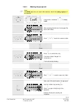
Page 78: ...tion VSD A F to display CodE When releasing the buttons 6 bars appear the first of which blinks or Press or to select a numeral or letter reset or Press reset to confirm the entry The value entered changes to a minus sign The next bar starts blinking reset or Press or to select a numeral or letter reset After entry of the last character the password must be confirmed by pressing reset Press reset ...

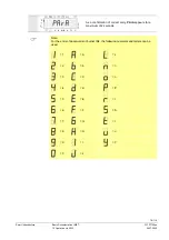
Page 79: ...ion via AZL2 24 07 2020 P V h min s Bild 48 0707 As a confirmation of correct entry PArA appears for a maximum of 2 seconds Note For the entry of passwords or burner IDs the following numerals and letters can be used 1 A L 2 b n 3 C o 4 d P 5 E r 6 F S 7 G t 8 H u 9 I Y 0 J ...

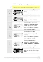
Page 80: ...tion appears blinking Proceed as described in section Entering the password and enter the former password After entry of the last character the password must be confirmed by pressing reset reset Letter n for new appears blinking Proceed as described in section Entering the password and enter the new password 4 characters After entry of the last character the password must be confirmed by pressing ...

Page 81: ...ocumentation LME7 CC1P7105en 13 Operation via AZL2 24 07 2020 Pressing the reset button takes you to parameter 041 heating engineer s password Continue in the parameter level to the next parameter group 100 End of the parameter level End ...

Page 82: ...the password must be confirmed by pressing reset reset Letter n for new appears blinking Proceed as described in section Entering the password and enter the new password 5 characters After entry of the last character the password must be confirmed by pressing reset reset Letter r for repeat appears blinking Proceed as described in section Entering the password and repeat entry of the new password ...

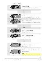
Page 83: ...nks display _ _ does not Press for parameter 060 Display Parameter 060 blinks index 00 and value 0 do not reset Press reset for parameter rEStorE Display Parameter rEStorE blinks Press for parameter bAC_UP Display Parameter bAC_UP blinks reset Press reset for the backup process Display Value 0 Press to shift the value to change mode one place to the left Display Value 0 blinks Note To identify dis...

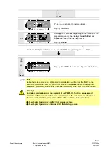
Page 84: ...am sequence the displays shows bAC End and signals the end of the backup process Display bAC End It will now be displayed for 2 minutes or can be finished by pressing the reset button 2 min or reset Display shows OFF when the backup process is finished Note The backup process saves all settings and parameters from the LME7 memory to the PME7 Warning If any parameters are changed a backup must be m...

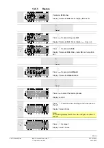
Page 85: ...1 blinks display _ _ does not Press for parameter 060 Display Parameter 060 blinks index 00 and value 0 do not reset Press reset for parameter rEStorE Display Parameter rEStorE blinks reset Press reset to select the restore process Display value 0 Press to shift the value to change mode one place to the left Display Value 0 blinks Note For realizing display faults the value change one place to the...

Page 86: ...restore process is finished Note During the restore process all settings and parameters are written from the PME7 to the internal memory of the LME7 As part of this process it is possible that previous program sequences parameters and settings in the internal memory of the LME7 will be overwritten Warning For initial commissioning or replacement of the PME7 the function sequence and parameter sett...

Page 87: ...on time 13 9 1 Parameters without index with direct display 13 9 1 1 Example of parameter 225 prepurge time on the parameter level P V h min s Bild 166 1107 Press for prepurge time Display Parameter 225 blinks value 3 675 does not reset or P V h min s Bild 167 1107 Press or for editing mode Display 3 675 or P V h min s Bild 168 1107 Press or to shift the former prepurge time to change mode one pla...

Page 88: ... V h min s Bild 166 1107 Alternative 2 Adopt the value reset P V h min s Bild 170 1107 Press reset to return to editing mode The value set will be adopted Note To detect display errors the value appears one place shifted to the right Display Value 3 822 ESC P V h min s Bild 212 1008 To the next parameter Back to the previous parameter ...

Page 89: ...fied time for air pressure signal Display Parameter 224 blinks characters _ _ do not reset P V h min s Bild 173 1107 Press reset for editing mode Display 48 510 or P V h min s Bild 174 1107 Press or to shift the former specified time to change mode one place to the left Display Specified time 48 510 blinks Note To detect display errors the value appears one place shifted to the left or P V h min s...

Page 90: ...ge reset P V h min s Bild 176 1107 Press reset to return to editing mode The value set will be adopted Note To detect display errors the value is shown again but shifted one place to the right Display Value 53 361 ESC P V h min s Bild 172 1107 Press ESC to return to the parameter level Display Parameter 224 blinks characters _ _ do not To the next parameter Back to the previous parameter ...

Page 91: ... the left the current error 701 appears blinking index 00 does not blink On the right error code 4 is displayed Example Parameter 701 index 00 error code 4 reset 1 3 s P V h min s Bild 205 1008 Press reset for 1 3 seconds to show index 00 for the error code blinking Display Parameter 701 does not blink index 00 blinks error 4 does not blink To the next index P V h min s Bild 206 1008 Press to sele...

Page 92: ...n s Bild 208 1008 Press to select the index 03 power value to the time of fault Example Parameter 701 index 03 power value 60 reset 1 3 s P V h min s Bild 209 1008 Press ESC to return to the index Display Parameter 701 does not blink index 03 blinks characters _ _ do not To the next index Back to the previous index P V h min s Bild 180 1107 When this display appears you have reached the end of the...

Page 93: ...to return to the parameter level Display Parameter 701 blinks index 01 and diagnostic code 4 do not To the next older error P V h min s Bild 210 1008 Parameters cover the period back to the last error since deletion of the history max to parameter 711 Example Parameter 711 index 00 To the next parameter Back to the previous parameter ...

Page 94: ...tment Loc 7 Loss of flame Too many losses of flame during operation restart limitation Faulty or soiled fuel valves Faulty or soiled flame detector Poor adjustment of burner Loc 8 Free Loc 9 Free Loc 10 Non volatile lockout with alarm output switched on at terminal X2 03 pin 3 fault lamp ON Wiring error or internal error other errors Loc 10 Non volatile lockout with alarm output switched off at te...

Page 95: ...ed high fire or Low fire 0 rpm or Maximum speed 0 rpm Loc 227 PWM fan faulty One or several parameters violate the minimum maximum limit rSt Er1 Error in compatibility between PME7 and LME7 during restore process Program sequence of PME7 does not match the LME7 rSt Er2 Error in compatibility between PME7 and LME7 during restore process LME7 hardware does not match the PME7 rSt Er3 Error during res...

Page 96: ...and Enter button Reset in the event of fault changeover visual diagnostic of the cause of fault see chapter Diagnostics of cause of fault button Display flame signal current 2 or phases display In lockout position MMI phase to the time of fault button Display flame signal current 1 or phases display In lockout position MMI phase to the time of fault 3 multicolor signal lamp See chapter Blink code ...

Page 97: ...ay in normal operation 15 2 1 Display in standby mode LCD Bild 02 0908 The LME7 is in standby 15 2 2 Display during startup shutdown 15 2 2 1 Display of program phases LCD Bild 03 0908 The LME7 is in phase 21 P21 The individual program phases are displayed in accordance with the program sequence For the color display of the signal lamp see List of phase display ...

Page 98: ...g Preignition time P40 Yellow flashing 1st safety time ignition transformer ON P42 Green Safety time ignition transformer OFF flame check P44 Green Interval End of safety time and fuel valve V1 ON Interval End of safety time and release of load controller Interval End of safety time and fuel valve V2 ON P50 Green 2nd safety time P54 Green Parameter 259 01 Actuator opens to a position low fire P54 ...

Page 99: ...tdown phases P01 Red yellow flashing Undervoltage P02 Yellow Safety loop open Safety shutdown followed by a non alterable lockout with interlocking P04 Red green flashing Extraneous light on burner startup timeout locking after 30 seconds P90 Yellow Pressure switch min open Safety shutdown followed by a non alterable lockout with interlocking Non alterable lockout LOC Red Lockout phase ...

Page 100: ...908 Display oP1 means stage 1 Display after oP is unit specific The signal lamp blinks green 15 3 Special functions 15 3 1 Manual lockout nfo and other button LCD Bild 06 0908 Alternately Press nfo simultaneously with any other button LME7 changes from any operating position directly to lockout Signal lamp lights up red Display shows current error code 167 ...

Page 101: ...isplayed alternately The LME7 is in lockout position The current error code is displayed and the signal lamp flashes red Example Error code 4 or LCD Bild 08 0908 Press or for display of the phase where the fault appeared Signal lamp blinks red Example Phase P02 A Only with modulation via analog signal Press A for display of the output position actuator position where the error occurred Signal lamp...

Page 102: ...1 3 seconds the flame signal current is displayed Signal lamp blinks green Example 11 3 s LCD Bild 11 0908 When pressing 3 seconds the point after the number begins to blink When the button is released the value is displayed for 2 minutes Signal lamp blinks green Then the normal display appears Display Point blinks value 11 does not 15 4 3 Reset nfo 1 s LCD Bild 02 0908 Press nfo for 1 to 3 second...

Page 103: ...of the relative current position Signal lamp blinks green The relative value 57 of the current position is displayed PME7 with actuator control Position of actuator 0 0 value of potentiometer 0 display Position of actuator high fire 0 90 value of potentiometer 1000 100 display 0 1000 PME7 with PWM fan Current speed 0 rpm 0 display Current speed corresponds to the rated load speed 100 display Examp...

Page 104: ...r the relative current speed of the PWM fan Signal lamp blinks green Display shows oP A 1 3 s Press A 1 3 seconds for display of the relative current position or the current speed Signal lamp blinks green The relative value 57 of the current position is displayed Position of actuator 0 0 value of potentiometer 0 display Position of actuator high fire 0 90 value of potentiometer 0 1000 100 display ...

Page 105: ...e 41 is displayed and the signal lamp blinks green Example Position of actuator or the current speed 41 based on range between high fire and 0 or 0 rpm A and or Press A simultaneously with or to adjust the actuator position or the fan speed between low fire x and high fire 100 Release the buttons when the required position or speed is reached Signal lamp blinks s green Example Value 43 Alternately...

Page 106: ...uring manual adjustment the display blinks The mode manual adjustment mode remains active until Escape is used to switch the LME7 back to normal operation or until the LME7 is reset via mains ON OFF This means that in the case of a new heat requirement and after startup the actuator or the PWM fan is driven to the position or speed of the manually preset value ...

Page 107: ...amp flashes yellow A short flash of the yellow signal lamp indicates that 3 seconds have passed Note If you press nfo for 3 seconds data download does not start To start the restore process again the LME7 must be reset by switching mains ON OFF Display shows run during download restore process of the program sequence Alternately Display shows alternately End and rSt Display shows the end of data e...

Page 108: ...908 Press nfo for 1 second to reset the LME7 Display OFF Warning For initial commissioning or replacement of the PME7 the function sequence and parameter settings must be checked on completion of the restore process See chapter Operation via AZL2 first startup restore See chapter Operation via internal LED first startup restore ...

Page 109: ... nfo 1 3 s run appears during download backup process of the program sequence Alternately Display shows alternately End and bAC Display shows the end of data exchange Display appears for 2 minutes or can be finished by pressing nfo nfo 1 s LCD Bild 02 0908 OFF is displayed when the backup process is complete Press nfo for 1 second to reset the LME7 Display OFF Warning If any parameters are changed...

Page 110: ...rnal LED 24 07 2020 15 7 1 Error during backup process Alternately Display shows alternately bAC and Er3 For meaning of a possible cause see chapter Error code list with operation via internal LED Note The backup process saves all settings and parameters from the LME7 memory to the PME7 ...

Page 111: ...meter rSt Display rSt nfo 1 3 s run appears during download restore process of program sequence Alternately Display shows alternately End and rSt Display shows the end of data exchange Signal lamp blinks red After 2 minutes the LME7 changes to Loc 138 LCD Bild 06 0908 Alternately After the restore process the LME7 is automatically in the lockout position Loc 138 and must be reset for operation nfo...

Page 112: ...on via internal LED Note During the restore process all settings and parameters are written from the PME7 to the internal memory of the LME7 As part of this process it is possible that previous program sequences parameters and settings in the internal memory of the LME7 will be overwritten 15 8 2 Reset nfo 1 s LCD Bild 02 0908 Press nfo for 1 to 3 seconds and OFF will appear When the button is rel...

Page 113: ...he OEM s password 82 Entering the password 78 Restore 85 Safety notes relating to operation 62 Service level 75 Display of service values 76 Display of the service level 75 End of service level 76 Error history 76 Intensity of flame 76 Mains voltage 76 Special functions 64 Manual lockout 64 B Basic unit Input gas pressure switch min 55 D Dimensions 42 LME7 42 F Function 43 Control sequence in the ...

Page 114: ...via analog input signal X65 59 Maximum possible resolution 59 Standardization of modulating range 59 Multistage modulating mode via 3 position step input X5 03 59 Maximum possible resolution 59 Multistage or modulating mode Relevant parameters 56 Setting the minimum power control step in modulating mode via analog input signal X65 60 Multistage or modulating mode with actuator 56 O Operation indic...

Page 115: ...115 116 Smart Infrastructure Basic Documentation LME7 CC1P7105en 15 Operation via internal LED 24 07 2020 Flame detectors 24 Pressure switch 25 Program module 19 Service tools 27 ...

Page 116: ...gram LME73 AGG9 52 Figure 12 Flame signal input terminal X10 06 53 Figure 13 Safety Loop terminal X3 04 54 Figure 14 Inputs for external load controller ON OFF terminal X5 03 54 Figure 15 Air pressure switch terminal X3 02 55 Figure 16 Connection diagram for feedback potentiometer ASZ12 33 56 Figure 17 Connection diagram for load controller 57 Figure 18 Description of the unit display and buttons ...

Reviews: