background image

Landis & Staefa Division

CC1N7421E

December 04, 1998

1/16

7

421

Burner Controls

LMG2...

Burner controls for the supervision of single- or two-stage forced draught gas or
gas / oil burners of small to medium capacity (typically up to 350 kW) in
intermittent operation.

The burner controls are certified to EN 230 and EN 298.

They carry the CE mark based on the directives for gas appliances and
electromagnetic compatibility.

The LMG2... and this data sheet are intended for use by OEMs which integrate the
burner controls in their products.

Burner controls of the LMG2... range are used for startup and supervision of single- or
two-stage gas or gas / oil burners in intermittent operation.
The flame is supervised with a detector electrode or UV flame detector QRA... (with
ancillary unit AGQ2...A27).

LMG21... / LMG22... in the same housing replace burner controls LGB21... / LGB22...
(refer to «Type summary») and, with the help of the respective adapters, burner controls
LFI7... and LFM1... (refer to «Ordering»).

Application-specific features

– 

Detection of undervoltages

– 

Air pressure supervision with function check of air pressure monitor during startup
and operation

– 

Electric remote reset

– 

Indication of error code and flame signal by means of LEDs in the lockout reset button

– 

Precise program times thanks to digital processing of signals

Available versions

• 

LMG21... / LMG22...

For unlimited burner capacities (output on startup 

 120 kW)

Locking in the event of loss of flame during operation

• 

LMG25...

For burner capacities 

 120 kW

Three repetitions in the event of loss of flame during
operation

ISO 9001

Use

Summary of Contents for LMG2 Series

Page 1: ...he flame is supervised with a detector electrode or UV flame detector QRA with ancillary unit AGQ2 A27 LMG21 LMG22 in the same housing replace burner controls LGB21 LGB22 refer to Type summary and with the help of the respective adapters burner controls LFI7 and LFM1 refer to Ordering Application specific features Detection of undervoltages Air pressure supervision with function check of air press...

Page 2: ... and commissioning work may only be carried out by qualified staff Observe the permissible length of the detector cables Refer to Technical data Always run ignition cables separate from the unit and other cables while observing the greatest possible distances Before putting the burner control into operation check wiring carefully Install switches fuses earthing etc in compliance with local regulat...

Page 3: ...ions Housing made of impact proof heat resistant plastic Housing accommodates the control of the microcontroller with PCB relay for load control electronic flame signal amplifier ionization lockout reset button with integrated red fault indication lamp and green flame signal lamp Made of impact proof heat resistant plastic Available with screw terminals AGK11 Cable entry optionally from the front ...

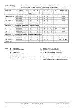
Page 4: ...6 3 8 3 12 12 Lockout or LMG22 230A273 8 20 3 2 6 3 8 3 16 5 16 5 Lockout UV detector QRA LMG22 233A27 8 20 3 2 6 3 8 3 30 30 Lockout with LMG22 330A273 8 30 3 2 6 3 8 3 12 11 Lockout AGQ2 A27 LMG22 330A2703 4 8 30 3 2 6 3 8 3 12 11 Lockout Burner controls for pre purging with low flame air volume without actuator control Detector electrode FE LMG25 230A27 8 20 3 2 6 2 8 5 Max 3 repetitions or LMG...

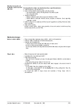
Page 5: ...0 V AGK25 To generate load on terminal 3 used with burners with no fan motor e g atmospheric gas burners Ancillary unit for UV supervision AGQ2 1A27 cable length 500 mm AGQ2 2A27 cable length 300 mm Can be fitted under the plug in base for dimensions refer to Dimensions Actuators refer to data sheet 7808 SQN3 Actuators refer to data sheet 7804 SQN7 Actuators refer to data sheet 7806 SQN9 Service a...

Page 6: ...itions class 2K2 Identification code to EN 298 Temperature range 40 60 C LMG21 LMG22 F T L L X N Humidity 95 r h LMG25 F T C L X N Mechanical conditions class 2M2 Operation IEC 721 3 3 CE conformity Climatic conditions class 3K5 According to the directives of the European Union Temperature range 20 60 C Electromagnetic compatibility EMC Humidity 95 r h 89 336 EEC incl 92 31 EEC Condensation format...

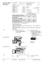
Page 7: ...er Ri 5 kΩ AC 50 µA Note With the same flame quality the detector current with LMG2 is lower than with LGB2 Flame supervision takes place by making use of the conductivity and rectifying effect of hot flame gases The flame signal amplifier responds only to the DC current component of the flame signal A short circuit between detector electrode and ground causes the burner to initiate lockout For de...

Page 8: ...max possible Measurement made on UV detector 200 µA 500 µA For UV detector QRA refer to data sheet 7712 Ancillary unit AGQ2 A27 When used in connection with burner controls LMG2 the UV ancillary unit AGQ2 A27 is required Using circuitry A or B the quench test on ageing UV detectors can be made in two different ways Type of circuitry A Operation with a permanent line UV test at twice the supply vol...

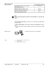
Page 9: ...If a fault occurs all outputs will immediately be deactivated 1 s On restoration of power a restart will be made with the full program sequence If the operating voltage drops below the undervoltage threshold for threshold refer to Functions a restart will be made with the full program sequence If there is a premature faulty flame signal during t1 Lockout If the contact of the air pressure monitor ...

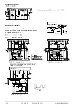
Page 10: ...e link required only with LGB21 not with LMG21 LMG25 12 2 10 8 3 6 11 7 4 5 1 R W G P SB HS 0 I L N AL EK2 M LP Z BV2 FE 7 4 2 1 a 0 6 0 5 9 8 BV1 LMG21 25 9 1 LMG2 4 12 5 LR SA O N O F F L SB R W BV1 RV BV2 7421a07 1098 12 2 10 8 3 6 11 9 7 4 5 1 HS 0 I N L AL EK2 M LP G P S B R W Z BV1 LR FE BV2 N 1 2 6 7 5 4 3 b1 b2 B a b III a3 a b II M S I a b a2 a b IV A a b V RV LK 74 2 1 a03 1 09 8 LMG21 2...

Page 11: ...S 0 I L N AL EK2 M LP Z BV2 FE 7 4 2 1 a 1 5 0 5 9 8 BV1 9 SA LMG22 LMG2 4 9 5 LR SA L SB R W BV1 RV BV2 7421a19 1098 12 12 2 10 8 3 6 11 9 5 7 4 1 G P S B R W AL E K 2 M LP LR Z B V1 FE B V2 L N 0 I H S N 8 1 2 7 5 6 3 4 9 7421a13 10 98 LK R V SA R 1 K 2 C 2 K 1 R 3 D R 2 C 1 I M S C 3 III II V LMG22 KL Zu III LKP NL t1 III t 7421d04 0498 I II t4 TSA 12 2 10 8 3 6 11 9 5 7 4 1 GP SB R W AL EK2 M ...

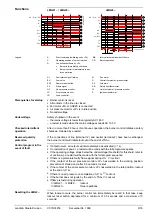
Page 12: ...Wire link MS Synchronous motor EK2 Remote lockout reset button NL Nominal load FE Detector electrode QRA UV detector FS Flame signal R Control thermostat pressurestat GP Gas pressure monitor RV Gas regulation damper HS Main switch SA Actuator SQN K1 4 Internal relays SB Safety limit thermostat KL Low flame t Time LK Air damper W Limit thermostat pressure monitor LKP Air damper position Z Ignition ...

Page 13: ... LP faulty LP incorrectly adjusted Fan motor does not run 4 x Air pressure monitor does not open or extraneous light on burner startup LP faulty LP incorrectly adjusted 5 x Extraneous light during pre purging Or internal device fault 7 x Loss of flame during operation Poor adjustment of burner Faulty or soiled fuel valves Short circuit between detector electrode and ground 8 17 x Free 18 x Air pre...

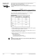
Page 14: ... 0 8 s 0 8 s 7 x 2 8 s 2 8 s 12 x 4 8 s The flame establishment time is the period of time from the moment BV1 opens to the moment the flame signal is detected for the first time The flame establishment time remains stored for one startup sequence and is re ascertained the next time the burner is started up During the period of time the flame establishment time is interrogated the fault status out...

Page 15: ...am LMG21 LMG25 NT 12 2 R W G P S B N AL K1 10 K2 7 Z 3 K3 K4 4 5 BV1 BV2 EK2 8 6 LP 11 FSV 1 FE Control of microcontroller 7421 a01 e 1 29 8 L Si M RESET EK FS green AL red LMG22 NT 12 2 R W G P S B N AL K1 1 0 K2 7 Z 3 K3 K4 4 5 BV1 BV2 E K 2 8 6 LP 11 FSV 1 FE Control of microcontroller RESET 7 421a02e 1298 9 M LR SA L EK Si M BV2 FS green AL red Legend ...

Page 16: ... using a metric screw with a lockwasher or similar Dimensions Burner control 5 5 62 5 9 25 25 88 91 1 41 5 22 46 5 62 7 4 2 1 m 0 1 0 3 9 8 TSA 3 sec CE 0085AT0010 9 5 5 0 12VA IP40 FS 3 sec Reset 3 sec Diagn AL 230 V 50 60 Hz Burner control with plug in base AGK11 and cable gland holders AGK65 can be inserted in the base Plug in base 7 4 2 1 m 0 2 0 3 9 8 24 24 30 30 11 4 5 Ø C B 4 1 7 2 3 5 A 16...

Reviews: