26/61
Building Technologies
Basic Documentation LMO39…
CC1P7154en
9 Operation, indication, diagnostics
15.03.2018
9 Operation, indication, diagnostics
9.1 Operation
EK
71
06
z0
1/
0
40
5
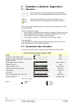
Lockout reset button is the key operating element for resetting the
burner control and for activating/deactivating the diagnostics functions.
LED
7
10
6
z0
2
e
/0
70
6
Red
Yellow
Green
The multicolor signal lamp in the lockout reset button is the key
indicating element for visual diagnostics and interface diagnostics.
Both (lockout reset button/signal lamp) are located under the transparent cover of the
lockout reset button.
There are 3 diagnostics choices:
1. Visual diagnostics: Operational status indication or diagnostics of the cause of fault
2. Interface diagnostics: With the help of the interface OCI400/OCI410 and the PC
software ACS410 or flue gas analyzers of different makes.
3. On the display of the AZL2… or BCI OCI410 and PC software ACS410
Visual diagnostics:
In normal operation, the different operating states are indicated in the form of color
codes according to the color code table given below.
9.2 Operational status indication
:
During startup, operation indication takes place according to the following table:
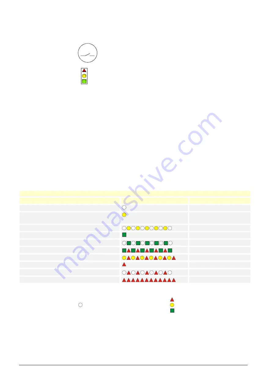
Color code table for multicolor signal lamp (LED)
Status
Color code
Color
Waiting time, other waiting states
........................................
OFF
Waiting for release of prepurging / postpurging by
oil pressure switch
........................................
Yellow
Ignition phase, ignition controlled
Flashing yellow
Operation, flame o.k.
.........................................
Green
Operation, flame not o.k.
Flashing green
Extraneous light on burner startup
Green-red
Undervoltage
Yellow-red
Fault, alarm
.........................................
Red
Error code output (see Error code table)
Flashing red
Interface diagnostics
Red flicker light
Table 6: Error code table
......
Steady on
Red
OFF
Yellow
Green
Legend

