background image

6/16 

Building Technologies Division 


CC1N7138en 


18.05.2016 

Operation, display, diagnostics 

EK

713

8z

04/

060

2


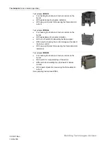
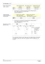
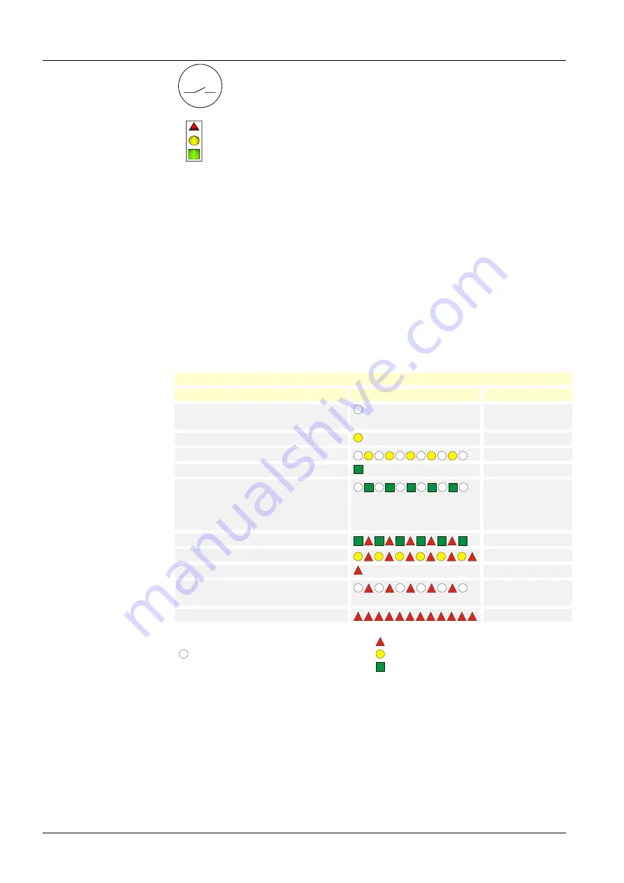
Lockout reset button «EK» is the key operating element for resetting 
the burner control and for activating / deactivating the diagnostic 
functions. 


LED

7138z

0

1e/

060

2

Red

Yellow

Green


The multicolor signal lamp (LED) in the lockout reset button is the key 
indicating element for visual diagnostics and interface diagnostics. 

 
Both elements (EK / LED) are located under the transparent cover of the lockout reset 
button. 
 
There are 2 diagnostic choices available: 
1.  Visual diagnostics: Operating state indication or diagnostics of the cause of fault 
2.  Interface diagnostics: With the help of the OCI400 interface and PC software 

ACS410 or flue gas analyzers of different makes. 
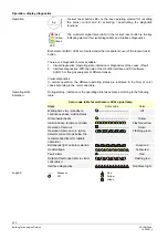
 
Visual diagnostics: 
In normal operation, the different operating states are indicated in the form of color 
codes according to the color code table. 
 
During startup, indication of the operating state takes place according to the following 
table: 
 

Color code table for multicolor «LED» signal lamp 

State 

Color code 

Color 

Waiting time «tw», standby on 
continuous phase, waiting status 

........................................ 

Off 

Oil preheater heats 

........................................


Yellow 

Ignition phase, ignition controlled 


Flashing yellow 

Operation, flame o.k. 

.........................................


Green 

Operation, flame not o.k. (when 
detector current drops below the 
recommended level for reliable 
operation) 


Flashing green 

Extraneous light on burner startup 


Green-red 

Undervoltage 


Yellow-red 

Fault, alarm 

.........................................


Red 

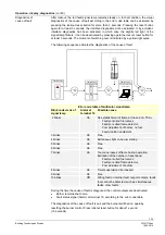
Output of fault code (refer to «Error 
code table») 


Flashing red 

Interface diagnostics 


Red flicker light 


...... 

Steady on 

Red 

Off 

Yellow 


Green 

Operation 

Operating state 
indication 

Legend 

Summary of Contents for LMO64 Series

Page 1: ...ning flames are supervised with photo resistive detectors QRB blue burning flames with blue flame detectors QRC Applications in accordance with EN 267 Automatic forced draft burners for liquid fuels Type tested and approved in accordance with DIN EN 298 Undervoltage detection Electrical remote reset Bridging contact for oil preheater Monitoring of time for oil preheater Accurate and reproducible p...

Page 2: ... reset button operation button of the LMO64 only manually applying a force of no more than 10 N without using any tools or pointed objects If not observed the safety functions are no longer ensured and there will be a risk of electric shock Fall or shock can adversely affect the safety functions Such units must not be put into operation even if they do not exhibit any damage If not observed the sa...

Page 3: ... the relevant regulations earthing the boiler alone does not suffice Commissioning notes When commissioning the plant or when doing maintenance work make the following safety checks Safety check Anticipated response a Burner startup with flame detector darkened Non alterable lockout at the end of the safety time TSA b Burner startup with flame detector ex posed to extraneous light Non alterable lo...

Page 4: ...ctrical connections The electrical connections of the LMO and the AGK11 comply with the requirements of EN 60335 2 102 EAC Conformity mark Eurasian Conformity mark ISO 9001 2008 ISO 14001 2004 OHSAS 18001 2007 China RoHS Hazardous substances table http www siemens com download A6V10883536 Service notes The service adapters can only be used for a short time They may only be used in supervised opera...

Page 5: ... base Burner controls type LMO64 and AGK11 6 plug in bases are silver grey RAL7001 The housing accommodates the microcontroller which controls the program sequence and the print relays for load control electronic flame signal amplifier lockout reset button with its integrated multicolor signal lamp for status and fault messages and the socket for connecting the OCI400 interface Multicolor display ...

Page 6: ... 300C2 LMO64 300C2 AC 230 V 1 30 kg h 2 5 s 15 16 s 10 s 15 s 10 s 20 s BPZ LMO64 301C2 LMO64 301C2 AC 230 V 1 30 kg h 2 5 s 15 16 s 10 s 15 s 10 s 90 s BPZ LMO64 302C2 LMO64 302C2 AC 230 V 1 30 kg h 2 5 s 15 16 s 10 s 15 s 3 s 20 s On request only Legend TSA Ignition safety time tw Waiting time t1 Prepurge time t1 Purge time t3 Preignition time t3n Postignition time t8 Postpurge time Bridging con...

Page 7: ...ls on the burner With signal lamps for program indication With on off switch for simulating the flame signal With holes for checking the control voltages at the tabs of the burner control With one pair of jacks for measuring the flame detector s resistance Test adapter KF8885 For checking the functions of burner controls on the burner With switch for manual startup of the burner With switch for si...

Page 8: ...se AGK11 Refer to Data Sheet N7201 Flame detectors Photo resistive detectors QRB1 Refer to Data Sheet N7714 Blue flame detectors QRC1 Refer to Data Sheet N7716 Frontal illumination Lateral illumination Service Tools Optical Interface OCI400 Optical interface between burner control and PC Facilitates viewing and recording setting parameters on site in connection with the ACS410 PC software Refer to...

Page 9: ...0 6 LMO64 Terminal 1 Max 5 A Terminals 3 and 8 Max 3 A Terminals 4 5 6 and 10 Max 1 A Storage DIN EN 60721 3 1 Climatic conditions Class 1K3 Mechanical conditions Class 1M2 Temperature range 20 60 C Humidity 95 r h Transport DIN EN 60721 3 2 Climatic conditions Class 2K2 Mechanical conditions Class 2M2 Temperature range 20 60 C Humidity 95 r h Operation DIN EN 60721 3 3 Climatic conditions Class 3...

Page 10: ...ation Flame signal stable Green signal lamp LED steady on QRB 45 µA 45 µA QRC 45 µA 45 µA The values given in the table above only apply under the following conditions Mains voltage depending on execution AC 230 V Ambient temperature 23 C QRB QRC 12 11 LMO bl µA DC QRB 7138v01 0602 sw 12 11 LMO 1 sw bl br µA DC QRC1 7138v02 0602 Legend µA DC DC microammeter with an internal resistance of Ri max 5 ...

Page 11: ...kout occurs after a maximum of 40 seconds No flame at the end of TSA Non alterable lockout at the end of the safety time TSA blink code 2 see Control sequence Flame is lost during operation Maximum of 3 repetitions then a non alterable lockout occurs Oil preheater s release contact does not close within 10 min Non alterable lockout After a non alterable lockout a reset can be carried out immediate...

Page 12: ...tware ACS410 or flue gas analyzers of different makes Visual diagnostics In normal operation the different operating states are indicated in the form of color codes according to the color code table During startup indication of the operating state takes place according to the following table Color code table for multicolor LED signal lamp State Color code Color Waiting time tw standby on continuou...

Page 13: ...n Fault position Fault position Error code table of multicolor signal lamp Blink code red of signal lamp Alarm at terminal 10 Possible cause 2 blinks On No establishment of flame at the end of TSA Faulty or soiled fuel valves Faulty or soiled flame detector Poor adjustment of burner no fuel Faulty ignition equipment 3 blinks On Free 4 blinks On Extraneous light on burner startup 5 blinks On Free 6...

Page 14: ...6 7 4 5 10 11 12 W SB R L N M Z BV1 AL Si 8 3 OW OH N 8 3 QRB QRC br bl sw 1 7138a01e 0908 9 EK2 EK1 µC control K1 K2 K3 FSV µC2 LED kbr µC1 Control sequence R OH OW M Z BV1 FS A A B C D 7 8 3 3 6 4 11 12 t1 t3 t3n TSA tw Z FS 6 11 12 7138d01fr 0516 Only with LMO64 302 reignition t3n t3n t1 1 W SB E t8 ...

Page 15: ...bl blue br brown sw black R Control thermostat or pressurestat SB Safety limit thermostat Si External primary fuse W Limit thermostat or pressure switch Z Ignition transformer TSA Ignition safety time tw Waiting time t1 Prepurge time t1 Purge time t3 Preignition time t3n Postignition time t8 Postpurge time A Beginning of startup sequence with burners using OH A Beginning of startup sequence with b...

Page 16: ...ivision CC1N7138en 18 05 2016 Dimensions Dimensions in mm 5 2 62 5 88 91 41 6 47 2 62 5 7138m05 1204 22 9 LMO64 2016 Siemens AG Building Technologies Division Berliner Ring 23 D 76437 Rastatt Subject to change Plug in base AGK11 6 ...

Reviews: