

9/16
Building Technologies Division
CC1N7138en
18.05.2016
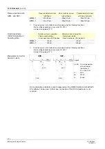
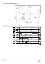
Legend
AL
Alarm device
BV...
Fuel valve
EK1
Lockout reset button
EK2
Remote lockout reset button
FS
Flame signal
FSV
Flame signal amplifier
K...
Contacts of control relay
kbr
Cable link (required only when oil preheater is not used)
LED
3-color signal lamps
M
Burner motor
OW
Release contact of oil preheater
OH
Oil preheater
QRB
Photo resistive detector
QRC
Blue-flame detector
bl = blue, br = brown, sw = black
R
Control thermostat or pressurestat
SB
Safety limit thermostat
Si
External primary fuse
W
Limit thermostat or pressure switch
Z
Ignition transformer
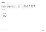
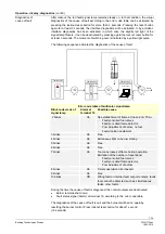
TSA
Ignition safety time
tw
Waiting time
t1
Prepurge time
t1´
Purge time
t3
Preignition time
t3n Postignition
time
t8 Postpurge
time
A´
Beginning of startup sequence with burners using «OH»
A
Beginning of startup sequence with burners using no «OH»
B
Time of flame establishment
C
Operating position
D
Controlled shutdown by «R»
E
End of startup sequence
Control signals
Required input signals
Permissible input signals
µC1 Mikrocontroller
1
µC2 Mikrocontroller
2


