
2/16
Building Technologies Division
CC1N7138en
18.05.2016
Accessories
(to be ordered separately)
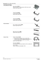
Connection accessories
for small burner controls
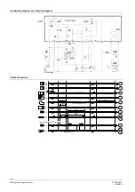
Plug-in base
AGK11.6
Plug-in base grey for connecting the LMO to burner plant
Refer to Data Sheet N7201
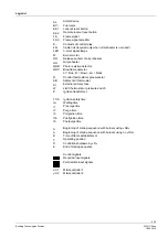
Cable holders
AGK66…
For plug-in base AGK11.
Refer to Data Sheet N7201
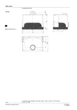
Cable holders
AGK65…
For plug-in base AGK11.
Refer to Data Sheet N7201
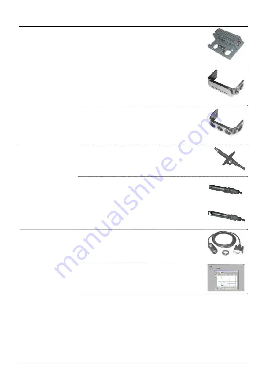
Flame detectors
Photo resistive detectors
QRB1...
Refer to Data Sheet N7714
Blue-flame detectors
QRC1...
Refer to Data Sheet N7716
Frontal illumination
Lateral illumination
Service-Tools
Optical Interface
OCI400
Optical interface between burner control and PC
Facilitates viewing and recording setting parameters on
site in connection with the ACS410 PC software
Refer to Data Sheet N7614
PC software
ACS410
PC software for setting the parameters and for visualizing the
burner controls
Refer to Software Documentation J7352


