LMV Series
Technical Instructions
LV5-1000
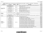
Menu Path
Parameter
Default
Range
Description
51.1
52.2
52.4
LEGEND -
Password Access:
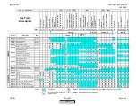
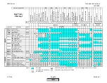
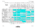
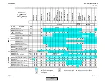
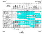
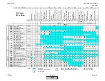
(U)=User, (S)=Service, (O)=OEM, Shaded = Commonly Used, ** = Must Set, X = Has Function, / = Partial Function
LMV
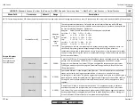
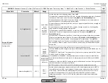
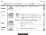
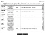
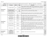
OperationTempGas(Oil) (S)
Displays the recorded flue gas recirculation temperatures for each point. This is recorded
when commissioning the ratio control curves.
x
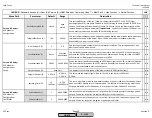
FGR MinPos (S)
0 deg
0-90 deg
Minimum angular position for the Aux 3 actuator when in temp.contr or TCautoDeact
operating modes. Serves as a default position if an auto deact occurs.
x
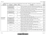
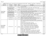
FGR MaxPos Fact (S)
10%
0-100%
Maximum value (limit on the Aux 3 actuator) calculated by comparing the current FGR
temperature to the stored values.
x
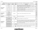
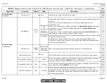
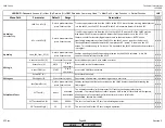
LC_OptgMode (U)
IntLC
ExtLC X5-03
IntLC
IntLC Bus
IntLC X62
ExtLC X62
ExtLC Bus
Current operating mode of the LMV5. Can also be changed at:
Params & Display >
LoadController > Configuration > LC_OptgMode
. If "Load Controller not active..." message
was seen under:
Params & Display > LoadController > Configuration > LC_OptgMode
, adjust
this parameter to "IntLC" and return to
Params & Display > LoadController > Configuration >
LC_OptgMode
.
x x x
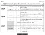
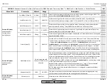
Ext Inp X62 U/I (S)
4..20 mA
4..20 mA
2..10 V
0..10 V
0..20 mA
See:
Params & Display > LoadController > Configuration > Ext Inp X62 U/I
x x x
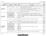
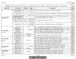
TL_Thresh_Off (S)
203 F
32-3632 F
See:
Params & Display > LoadController > TempLimiter > TL_ThreshOff
x x x
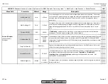
TL_SD_On (S)
-5%
-50-0%
See:
Params & Display > LoadController > TempLimiter > TL_SD_On
x x x
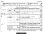
Sensor Select (S)
Pt100
Pt100
Pt1000
Ni1000
TempSensor
PressSensor
Pt100Pt1000
Pt100Ni1000
NoSensor
See:
Params & Display > LoadController > Configuration > Sensor Select
x x x
MeasureRangePtNi (S)
302 F
302 F
752 F
1562 F
See:
Params & Display > LoadController > Configuration > MeasureRangePtNi
x x x
Params & Display>
SystemConfig
Read Only
Params & Display>
SystemConfig>
TempLimiter
Params & Display>
Flue Gas Recirc.
SCC Inc.
Page 43
Section 3
HOME
HOME
P - LIST
Summary of Contents for LMV 5 Series
Page 2: ...Intentionally Left Blank ...
Page 41: ...LMV Series Technical Instructions Document No LV5 1000 SCC Inc Page 7 Section 2 HOME ...
Page 42: ...Technical Instructions LMV Series Document No LV5 1000 Section 2 Page 8 SCC Inc HOME ...
Page 43: ...LMV Series Technical Instructions Document No LV5 1000 SCC Inc Page 9 Section 2 HOME ...
Page 44: ...Technical Instructions LMV Series Document No LV5 1000 Section 2 Page 10 SCC Inc HOME ...
Page 45: ...LMV Series Technical Instructions Document No LV5 1000 SCC Inc Page 11 Section 2 HOME ...
Page 46: ...Technical Instructions LMV Series Document No LV5 1000 Section 2 Page 12 SCC Inc HOME ...
Page 47: ...LMV Series Technical Instructions Document No LV5 1000 SCC Inc Page 13 Section 2 HOME ...
Page 48: ...Technical Instructions LMV Series Document No LV5 1000 Section 2 Page 14 SCC Inc HOME ...
Page 49: ...LMV Series Technical Instructions Document No LV5 1000 SCC Inc Page 15 Section 2 HOME ...
Page 50: ...Technical Instructions LMV Series Document No LV5 1000 Section 2 Page 16 SCC Inc HOME ...
Page 51: ...LMV Series Technical Instructions Document No LV5 1000 SCC Inc Page 17 Section 2 HOME ...
Page 52: ...Technical Instructions LMV Series Document No LV5 1000 Section 2 Page 18 SCC Inc HOME ...
Page 53: ...LMV Series Technical Instructions Document No LV5 1000 SCC Inc Page 19 Section 2 HOME ...
Page 54: ...Technical Instructions LMV Series Document No LV5 1000 Section 2 Page 20 SCC Inc HOME ...
Page 55: ...LMV Series Technical Instructions Document No LV5 1000 SCC Inc Page 21 Section 2 HOME ...
Page 373: ...Intentionally Left Blank ...

