Technical
Instructions
LMV
Series
Document
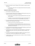
No.
LV5
‐
1000
Section
4
Page
18
SCC
Inc.
NOTE:
While
commissioning
the
Ratio
Control
Curves,
it
is
the
responsibility
of
the
technician
to
ensure
that
safe
fuel
/
air
ratios
are
being
maintained.
If
an
AZL5
arrow
key
is
held
down
when
adjusting
an
actuator
position,
the
position
will
be
changed
at
a
progressively
faster
rate
.
5.
Set
the
load
number
to
100%.
Increase
the
effective
firing
rate
of
the
burner
by
increasing
the
actuator
and
/
or
VSD
positions
in
a
way
that
maintains
a
safe
fuel
/
air
ratio.
This
is
typically
accomplished
by
increasing
air,
fuel
and
VSD
(if
equipped)
in
a
stepwise
rotation.
Keep
increasing
the
firing
rate
in
this
manner
until
high
fire
positions
of
the
actuators
/
VSD
are
reached.
NOTE:
Typically,
the
gas
pressure
regulator
immediately
upstream
of
the
firing
rate
control
valve
will
need
to
be
adjusted
on
a
new
installation.
Adjust
the
regulator
such
that
the
firing
rate
control
valve
is
between
60
‐
80
degrees
open
at
high
fire.
6.
Once
high
fire
actuator
/
VSD
positions
and
gas
pressure
regulator(s)
are
set,
record
actuator
/
VSD
positions,
burner
head
pressure,
high
fire
fuel
flow,
and
gas
pressure
upstream
of
the
firing
rate
control
valve.
After
this
is
recorded,
the
burner
can
be
shut
down.
7.
With
the
burner
off,
go
back
to
Point
1.
When
Point
1
is
entered,
the
AZL
will
prompt
to
“change”
or
“delete”
the
point.
“Delete”
should
be
selected,
and
Point
1
should
be
deleted.
8.
Now
that
low
fire
and
high
fire
fuel
flows
have
been
established
and
the
gas
pressure
regulator
has
been
set,
the
Ratio
Control
Curves
can
be
laid
out
using
fuel
flow.
If
fuel
flow
is
not
available,
burner
head
pressure
can
be
used
as
a
last
resort.
The
curves
can
be
laid
out
using
paper
and
a
calculator,
or
a
free
excel
spreadsheet
is
available
for
this
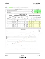
purpose.
This
spreadsheet,
called
the
“LMVx
Curves
Spreadsheet”,
can
be
found
at
www.scccombustion.com.
The
next
page
shows
how
the
“LMVx
Curves
Spreadsheet”
used
to
set
up
a
600
BHP
steam
boiler
with
FGR
(Aux
3
actuator)
and
a
VSD.
This
is
an
example
to
illustrate
what
a
typical
setup
might
look
like,
and
is
not
intended
to
be
copied
verbatim
to
an
LMV5
in
the
field.
NOTE:
Up
to
15
curve
points
can
be
entered;
however,
10
points
are
recommended
for
most
applications.
HOME
Summary of Contents for LMV 5 Series
Page 2: ...Intentionally Left Blank ...
Page 41: ...LMV Series Technical Instructions Document No LV5 1000 SCC Inc Page 7 Section 2 HOME ...
Page 42: ...Technical Instructions LMV Series Document No LV5 1000 Section 2 Page 8 SCC Inc HOME ...
Page 43: ...LMV Series Technical Instructions Document No LV5 1000 SCC Inc Page 9 Section 2 HOME ...
Page 44: ...Technical Instructions LMV Series Document No LV5 1000 Section 2 Page 10 SCC Inc HOME ...
Page 45: ...LMV Series Technical Instructions Document No LV5 1000 SCC Inc Page 11 Section 2 HOME ...
Page 46: ...Technical Instructions LMV Series Document No LV5 1000 Section 2 Page 12 SCC Inc HOME ...
Page 47: ...LMV Series Technical Instructions Document No LV5 1000 SCC Inc Page 13 Section 2 HOME ...
Page 48: ...Technical Instructions LMV Series Document No LV5 1000 Section 2 Page 14 SCC Inc HOME ...
Page 49: ...LMV Series Technical Instructions Document No LV5 1000 SCC Inc Page 15 Section 2 HOME ...
Page 50: ...Technical Instructions LMV Series Document No LV5 1000 Section 2 Page 16 SCC Inc HOME ...
Page 51: ...LMV Series Technical Instructions Document No LV5 1000 SCC Inc Page 17 Section 2 HOME ...
Page 52: ...Technical Instructions LMV Series Document No LV5 1000 Section 2 Page 18 SCC Inc HOME ...
Page 53: ...LMV Series Technical Instructions Document No LV5 1000 SCC Inc Page 19 Section 2 HOME ...
Page 54: ...Technical Instructions LMV Series Document No LV5 1000 Section 2 Page 20 SCC Inc HOME ...
Page 55: ...LMV Series Technical Instructions Document No LV5 1000 SCC Inc Page 21 Section 2 HOME ...
Page 373: ...Intentionally Left Blank ...

