Technical
Instructions
LMV
Series
Document
No.
LV5
‐
1000
Section
4
Page
28
SCC
Inc.
Additional
Tips
for
Commissioning
If
an
LMV52
is
being
commissioned,
activate
the
O
2
sensor
as
soon
as
possible.
Once
the
O
2
sensor
is
heated,
this
will
show
a
fast
responding
O
2
value
on
the
AZL
screen
during
Ratio
Control
Curve
commissioning.
This
sensor
reads
%O
2
wet
so
the
value
will
be
somewhat
lower
than
an
external
flue
gas
analyzer.
Using
a
fuel
flow
meter
(temporary
or
permanent)
for
commissioning
is
always
a
good
idea
even
for
LMV51’s
without
O
2
trim.
If
the
fuel
input
(heat
output)
increases
linearly
with
firing
rate,
the
PID
loop
in
any
load
control
will
work
much
better.
A
temporary,
insertion
type
of
flow
meter
is
available
from
SCC
Inc.
for
this
purpose.
If
burner
head
pressure
must
be
used
as
a
last
resort
to
estimate
firing
rate,
bear
in
mind
that
head
pressure
does
not
increase
with
gas
flow
in
a
linear
manner.
There
is
a
square
root
relationship
between
the
differential
pressure
across
the
burner
head
and
the
gas
flow.
This
relationship
is
very
similar
to
how
the
pressure
varies
across
a
fixed
orifice
with
an
increase
or
decrease
in
flow.
Also,
furnace
pressure
must
be
accounted
for
by
hooking
up
both
sides
of
the
manometer,
one
side
to
the
burner
head
pressure
and
one
side
to
the
furnace
pressure.
Carbon
Monoxide
(CO)
is
produced
when
combustion
is
incomplete,
typically
due
to
the
flame
being
too
rich
or
too
lean.
CO
is
potentially
explosive
when
mixed
with
air
in
the
right
proportions.
For
CO
to
be
explosive
in
air,
it
must
reach
a
concentration
of
at
least
12.5%
(125,000
ppm)
with
an
ignition
source
present.
If
a
burner
is
commissioned
properly,
actuator
curves
should
increase
smoothly
with
increasing
load
(firing
rate).
One
exception
to
this
would
be
the
FGR
actuator
(Aux1
or
Aux3)
which
commonly
decreases
(closes)
as
firing
rate
increases.
Curves
should
always
be
smooth,
with
no
sharp
corners.
The
best
and
fastest
method
to
commission
a
burner
with
an
LMV5
is
to
set
up
a
small
table
where
the
technician
can
have
his
laptop,
AZL,
fuel
flow
meter
and
external
flue
gas
analyzer
all
within
arm's
reach.
This
allows
the
curve
points
to
be
input
rapidly
and
accurately.
If
the
information
is
entered
in
the
laptop
point
by
point,
a
very
nice
start
‐
up
report
will
also
be
generated.
The
ACS450
software
is
not
as
fast
as
using
the
AZL
to
commission
the
LMV5.
Since
this
is
the
case,
the
ACS450
is
typically
not
used
to
commission
the
LMV5.
However,
the
ACS450
is
very
valuable
when
used
to
download
an
.mdb
file
(all
parameter
settings,
fault
and
lockout
history,
in
English)
and
also
when
used
to
download
.par
files
(the
machine
‐
language
parameter
set
from
the
LMV5).
It
is
recommended
to
download
both
of
these
files
after
commissioning,
so
that
there
is
a
backup
record
of
all
parameter
and
curve
settings.
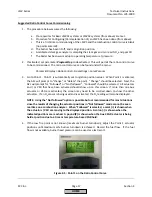
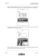
To
go
back
out
of
the
menu
and
check
burner
operation,
press
the
<
and
>
buttons
at
the
same
time.
This
will
take
the
cursor
to
Normal
Operation,
so
the
normal
operation
screen
can
be
viewed
by
pressing
Enter.
This
can
be
done
anywhere
in
the
menu
as
long
as
a
single
parameter
is
not
currently
displayed.
Pressing
Esc
will
take
the
cursor
back
in
to
where
it
was
in
the
menu.
HOME
Summary of Contents for LMV 5 Series
Page 2: ...Intentionally Left Blank ...
Page 41: ...LMV Series Technical Instructions Document No LV5 1000 SCC Inc Page 7 Section 2 HOME ...
Page 42: ...Technical Instructions LMV Series Document No LV5 1000 Section 2 Page 8 SCC Inc HOME ...
Page 43: ...LMV Series Technical Instructions Document No LV5 1000 SCC Inc Page 9 Section 2 HOME ...
Page 44: ...Technical Instructions LMV Series Document No LV5 1000 Section 2 Page 10 SCC Inc HOME ...
Page 45: ...LMV Series Technical Instructions Document No LV5 1000 SCC Inc Page 11 Section 2 HOME ...
Page 46: ...Technical Instructions LMV Series Document No LV5 1000 Section 2 Page 12 SCC Inc HOME ...
Page 47: ...LMV Series Technical Instructions Document No LV5 1000 SCC Inc Page 13 Section 2 HOME ...
Page 48: ...Technical Instructions LMV Series Document No LV5 1000 Section 2 Page 14 SCC Inc HOME ...
Page 49: ...LMV Series Technical Instructions Document No LV5 1000 SCC Inc Page 15 Section 2 HOME ...
Page 50: ...Technical Instructions LMV Series Document No LV5 1000 Section 2 Page 16 SCC Inc HOME ...
Page 51: ...LMV Series Technical Instructions Document No LV5 1000 SCC Inc Page 17 Section 2 HOME ...
Page 52: ...Technical Instructions LMV Series Document No LV5 1000 Section 2 Page 18 SCC Inc HOME ...
Page 53: ...LMV Series Technical Instructions Document No LV5 1000 SCC Inc Page 19 Section 2 HOME ...
Page 54: ...Technical Instructions LMV Series Document No LV5 1000 Section 2 Page 20 SCC Inc HOME ...
Page 55: ...LMV Series Technical Instructions Document No LV5 1000 SCC Inc Page 21 Section 2 HOME ...
Page 373: ...Intentionally Left Blank ...

