Technical
Instructions
LMV
Series
Document
No.
LV5
‐
1000
Section
5
Page
10
SCC
Inc.
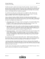
The
purpose
of
the
standardization
(calibration)
procedure
is
to
establish
the
relationship
between
the
LMV52
analog
output
signal
(4
‐
20mA)
and
the
blower
speed,
as
read
by
the
speed
sensor
connected
to
the
LMV52.
This
is
done
by
recording
a
blower
speed
with
19.5
mA
applied
to
the
VFD.
Once
started,
basic
steps
in
the
standardization
are
as
follows:
1.
The
air
damper
is
opened
to
pre
‐
purge
position.
2.
The
run
/
stop
dry
contact
in
the
LMV52
is
closed.
3.
An
analog
signal
of
19.5
mA
is
applied
to
the
VFD.
4.
The
VFD
/
blower
ramp
up
to
speed.
After
the
speed
has
stabilized,
the
actual
peak
RPM
is
recorded
by
the
LMV52.
5.
The
analog
signal
is
returned
to
minimum
(typically
4
mA).
6.
The
run
/
stop
dry
contact
in
the
LMV52
is
opened.
7.
The
air
damper
is
returned
to
home
position.
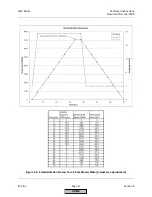
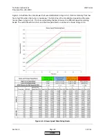
A
typical
standardization
process
for
a
2
‐
pole
(~3600
RPM)
blower
is
shown
graphically
in
Figure
5
‐
3.
If
a
standardization
was
performed
on
a
4
‐
pole
(~1800
RPM)
blower,
the
procedure
would
be
similar
but
the
blower
speed
achieved
at
19.5
mA
would
be
approximately
1750
RPM.
HOME
Summary of Contents for LMV 5 Series
Page 2: ...Intentionally Left Blank ...
Page 41: ...LMV Series Technical Instructions Document No LV5 1000 SCC Inc Page 7 Section 2 HOME ...
Page 42: ...Technical Instructions LMV Series Document No LV5 1000 Section 2 Page 8 SCC Inc HOME ...
Page 43: ...LMV Series Technical Instructions Document No LV5 1000 SCC Inc Page 9 Section 2 HOME ...
Page 44: ...Technical Instructions LMV Series Document No LV5 1000 Section 2 Page 10 SCC Inc HOME ...
Page 45: ...LMV Series Technical Instructions Document No LV5 1000 SCC Inc Page 11 Section 2 HOME ...
Page 46: ...Technical Instructions LMV Series Document No LV5 1000 Section 2 Page 12 SCC Inc HOME ...
Page 47: ...LMV Series Technical Instructions Document No LV5 1000 SCC Inc Page 13 Section 2 HOME ...
Page 48: ...Technical Instructions LMV Series Document No LV5 1000 Section 2 Page 14 SCC Inc HOME ...
Page 49: ...LMV Series Technical Instructions Document No LV5 1000 SCC Inc Page 15 Section 2 HOME ...
Page 50: ...Technical Instructions LMV Series Document No LV5 1000 Section 2 Page 16 SCC Inc HOME ...
Page 51: ...LMV Series Technical Instructions Document No LV5 1000 SCC Inc Page 17 Section 2 HOME ...
Page 52: ...Technical Instructions LMV Series Document No LV5 1000 Section 2 Page 18 SCC Inc HOME ...
Page 53: ...LMV Series Technical Instructions Document No LV5 1000 SCC Inc Page 19 Section 2 HOME ...
Page 54: ...Technical Instructions LMV Series Document No LV5 1000 Section 2 Page 20 SCC Inc HOME ...
Page 55: ...LMV Series Technical Instructions Document No LV5 1000 SCC Inc Page 21 Section 2 HOME ...
Page 373: ...Intentionally Left Blank ...

